
Pixel device of a transflective-type LCD panel

Active Publication Date: 2005-04-21
AU OPTRONICS CORP
View PDF2 Cites 41 Cited by
  • Summary
  • Abstract
  • Description
  • Claims
  • Application Information

AI Technical Summary

Benefits of technology

[0014] The object of the present invention is to promote the visibility of the transflective LCD and change the amount of retardation in the reflective region and the transmission region thereof by controlling the electric field strength thereof of the transflective LCD.

Problems solved by technology

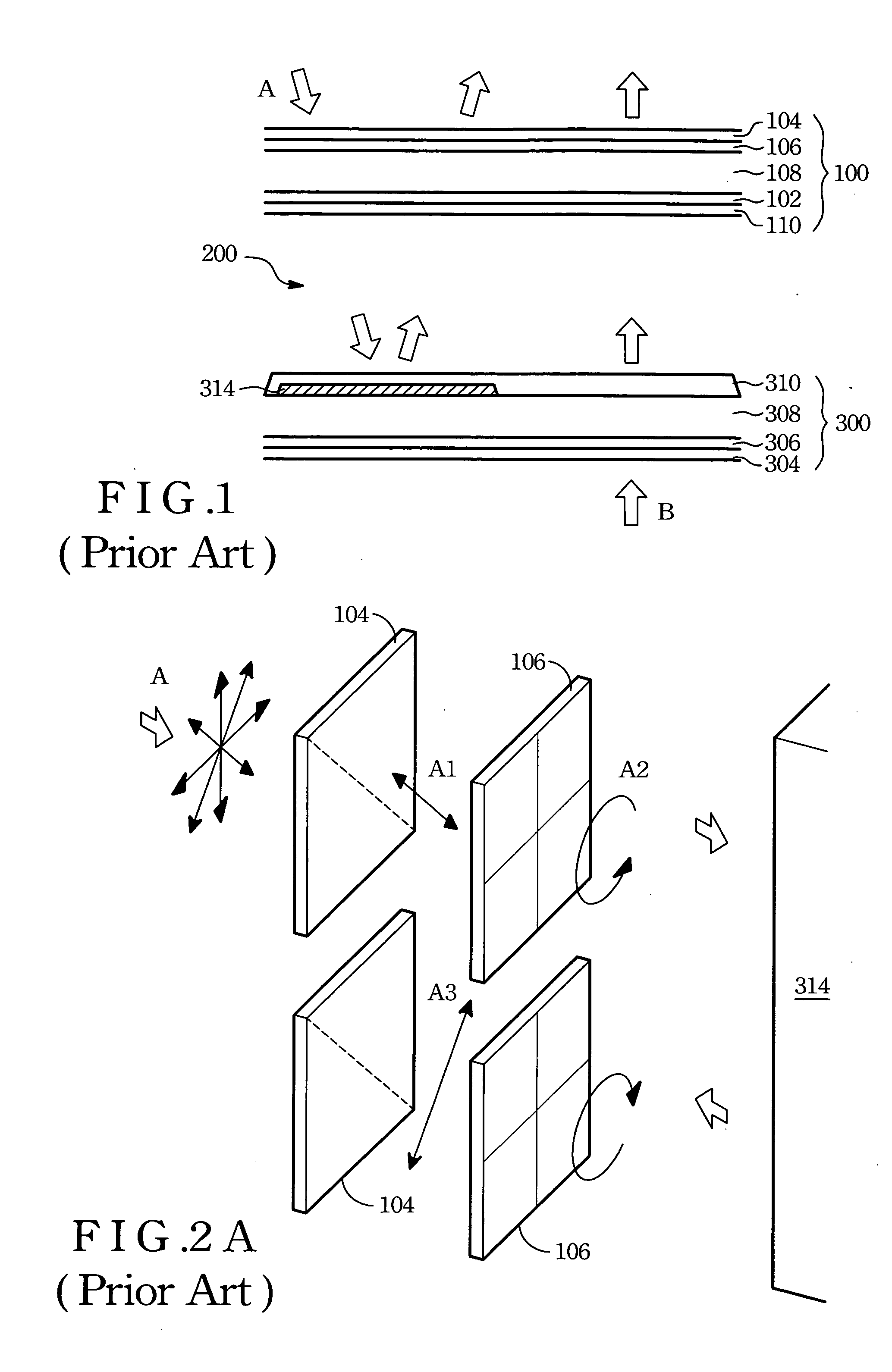
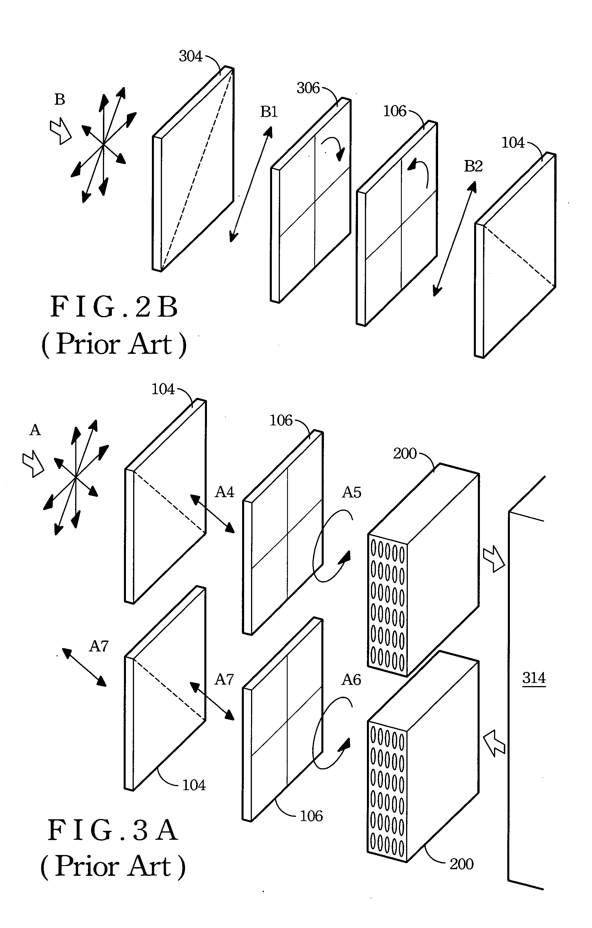
However, visibility of the reflective LCD is poor when the environment is too dark to provide enough ambient light.

Method used


Image

  • Pixel device of a transflective-type LCD panel
  • Pixel device of a transflective-type LCD panel
  • Pixel device of a transflective-type LCD panel

Examples


Embodiment Construction

[0028] The invention disclosed herein is directed to a pixel device of a transflective LCD. In the following description, numerous details are set forth in order to provide a thorough understanding of the present invention. It will be appreciated by one skilled in the art that variations of these specific details are possible while still achieving the results of the present invention. In other instance, well-known components are not described in detail in order not to unnecessarily obscure the present invention.

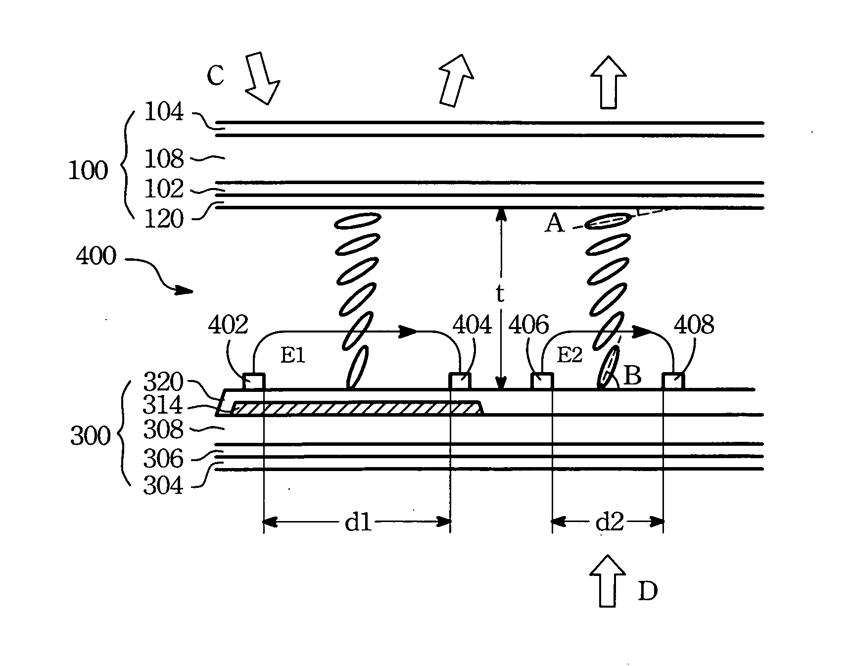
[0029]FIG. 4 is a schematic cross-sectional view of a pixel device of a transflective LCD according to the present invention. The pixel device comprises an upper panel 100, a lower panel 300, and an interposed nematic LC layer 400. The upper panel 100 includes a glass substrate 108 as a main body, a polarizer 104 formed on the glass substrate 108, and a color filter 102 and a first alignment layer 120 stacked on a lower surface of the glass substrate 108. The first alignment...


PUM


Abstract

A pixel device of a transflective liquid crystal display (LCD) having a hybrid alignment nematic liquid crystal layer driven by a lateral electric field. The pixel device of the transflective LCD includes an upper panel and a lower panel, in which the lower panel has an upper surface divided into a reflective region covered with a reflector and a remainder transmission region.

Description

BACKGROUND OF THE INVENTION [0001] (1) Field of the Invention [0002] The present invention relates to a pixel device of a transflective liquid crystal display (LCD), and more particularly to a pixel device having a hybrid alignment nematic liquid crystal layer driven by a lateral electric field. [0003] (2) Description of Related Art [0004] Along with enormous promotions upon thin film transistor (TFT) fabrication technique, liquid crystal displays (LCD) are broadly adopted to personal digital assistants (PDA), notebooks (NB), digital cameras (DC), digital videos (DV), mobile phones, etc. In an LCD panel, a cold cathode fluorescent lamp (CCFL) is included as a backlight source. The backlight source provides light to pass through layers of optical films including a diffusion film, a polarizer, etc., and to thereafter form a uniform planar image on the LCD. [0005] Generally, most of light emitted from the backlight source is absorbed while passing through the optical films and the liqu...

Claims


Application Information

Patent Timeline
IPC IPC(8): G02F1/1335G02F1/13363G02F1/1343G02F1/139
CPCG02F1/133555G02F2001/133638G02F1/1393G02F1/134363G02F1/133638
Inventor LIN, CHING-HUAN
Owner AU OPTRONICS CORP
Learn More