
Multi-angle viewable indicator apparatus

Inactive Publication Date: 2006-03-07
ROCKWELL TECH
View PDF16 Cites 18 Cited by
  • Summary
  • Abstract
  • Description
  • Claims
  • Application Information

AI Technical Summary

Benefits of technology

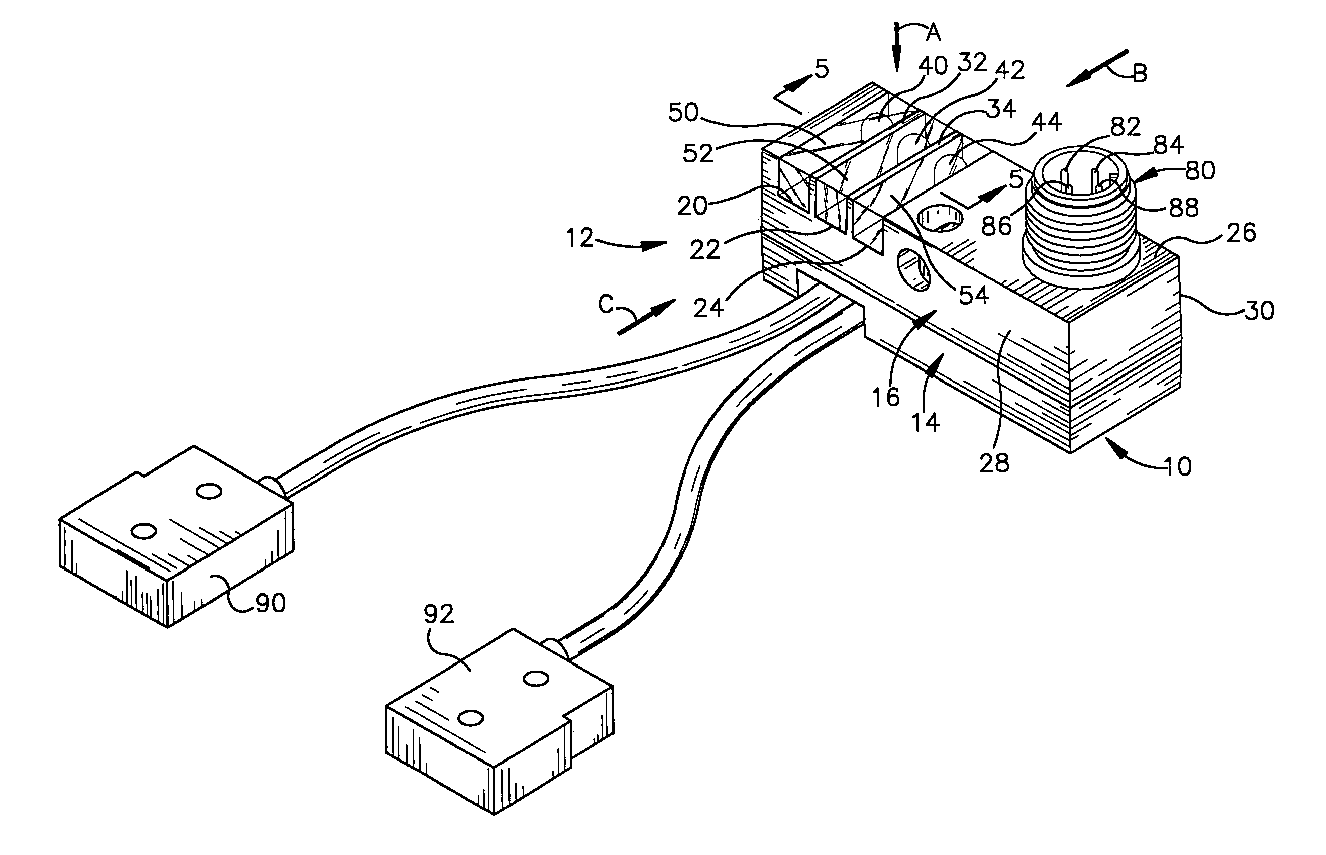
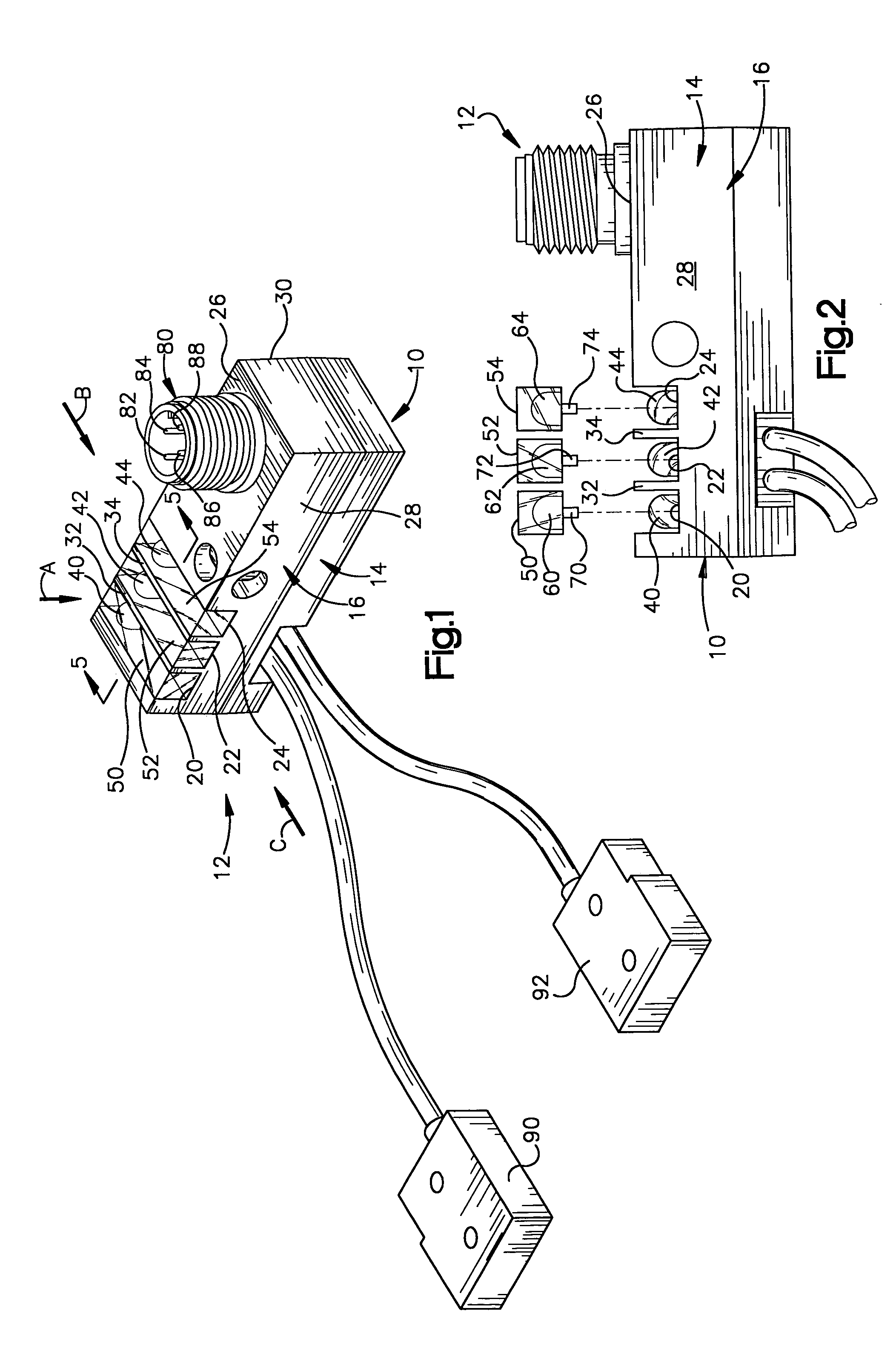
[0005]The present invention relates to an indicator apparatus that facilitates visibility of one or more indicators from multiple viewing angles relative to the apparatus. The indicator apparatus includes a housing having an outer sidewall portion. The sidewall portion, for example, has a first side extending between two adjacent sides. One or more elongated slots are formed in the sidewall portion. A substantially translucent material is disposed in the slot so that the translucent material is visible from more than one side of the housing, such as the first side and another side through which the slot extends. A light source is operatively associated with the substantially translucent material for illuminating the material. As a result, when the light source illuminates the substantially translucent material, the illuminated material is visible from more than one side of the housing. In accordance with a specific aspect of the present invention, the light sources are recessed relative to the outer sidewall of the housing so as to mitigate damage to the light source when used in an industrial environment.

Problems solved by technology

While a conventional indicator mounting arrangement may be able to provide desired information about the operating condition of the sensor at the housing, the indicators often are not visible from different viewing angles.
If the LEDs are arranged to extend outwardly from the housing so as to be sufficiently visible from different viewing angles, however, they are exposed to hazards of the operating environment in which the sensor is employed.

Method used


Image

  • Multi-angle viewable indicator apparatus
  • Multi-angle viewable indicator apparatus
  • Multi-angle viewable indicator apparatus

Examples


Embodiment Construction

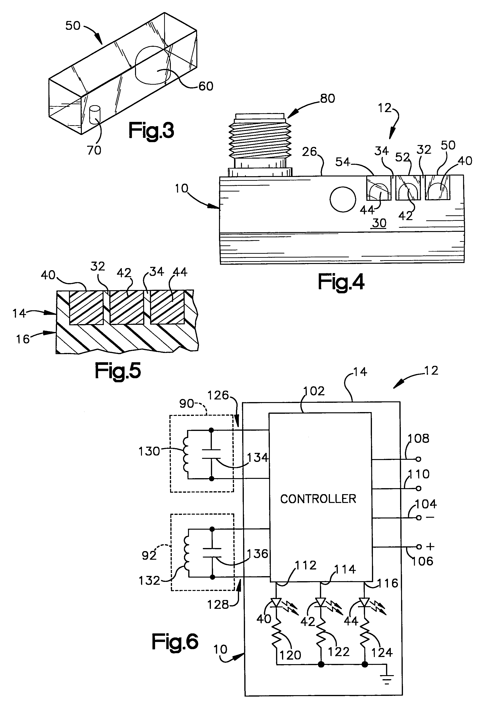
[0017]Various aspects of the present invention are described below in connection with FIGS. 1–6 in which like reference characters refer to like parts throughout the various views.

[0018]FIG. 1 illustrates an indicator apparatus 10, in accordance with an aspect of the present invention. While the particular indicator apparatus 10 is illustrated as being implemented as part of a proximity sensor system 12, those skilled in the art will appreciate that the indicator apparatus is applicable to other types of systems and devices and that all such uses are contemplated as being within the scope of the present invention.

[0019]The system 10 includes a housing 14 having an outer sidewall portion 16. For example, the sidewall portion 16 is a rectangular cylinder, although other shapes of housings (e.g., circular cylinder, etc.) also may be implemented in accordance with the present invention.

[0020]One or more slots 20, 22, and 24 extend through the sidewall portion 16 of the housing 14. By wa...


PUM


Abstract

An indicator apparatus facilitates visibility of one or more indicators from multiple angles. The apparatus includes a housing having an outer sidewall portion. The sidewall portion, for example, has a first side extending between two adjacent sides. One or more elongated slots are formed in the sidewall portion. A substantially translucent material is disposed in the slot so that the translucent material is visible from more than one side of the housing, such as the first side and another side through which the slot extends. A light source is operatively associated with the substantially translucent material for illuminating the material. As a result, when the light source illuminates the substantially translucent material, the illuminated translucent material is visible from more than one side of the housing.

Description

TECHNICAL FIELD[0001]The present invention generally relates to an indicator arrangement and, more particularly, to an indicator apparatus having one or more indicators that are viewable from multiple directions.BACKGROUND[0002]Various types of proximity sensors are used for detecting the presence or absence of an object. Common types of non-contact proximity sensors include inductive proximity sensors, capacitive proximity sensors, ultrasonic proximity sensors, and photoelectric sensors. Such sensors, for example, may be used in motion or position applications, conveyor system control applications, process control applications, robotic welding applications, machine control applications, liquid level detection applications, as well as other known applications.[0003]An inductive proximity sensor, for example, includes an oscillator that provides an oscillating signal to an inductive coil, which provides an electromagnetic field at a predetermined frequency. As an electrically conduct...

Claims


Application Information

Patent Timeline
IPC IPC(8): G08B5/00G08B21/00H01H9/16H03K17/945
CPCH03K17/945H01H9/161
Inventor SHAFIYAN-RAD, SAEEDCORBOSIERO, JR., DANIEL M.SCHLADENHAUFFEN, MARK STEPHEN
Owner ROCKWELL TECH
Learn More