
Cassette for holding a planar light source with a thermally isolated driver board

a driver board and case technology, applied in the field of lighting systems, can solve the problems of affecting the operation of the oled, presenting challenges to lighting designers, and the relative difficulty of flat panel light sources to integrate into the structural environment of the luminaire or lighting system,

Active Publication Date: 2020-01-28
ABL IP HLDG
View PDF14 Cites 0 Cited by
  • Summary
  • Abstract
  • Description
  • Claims
  • Application Information

AI Technical Summary

Benefits of technology

[0005]The present invention is directed to a means for mechanically holding a planar light source and a driver board so that the light source together with the driver board can be operatively and releasably connected to a luminaire or lighting system. The invention incorporates the light source and driver board into the luminaire or lighting system structure in a manner that is compatible with low profile components and that is aesthetically pleasing and also maintains the light source and driver board in thermal isolation from one another to prevent heat produced by the driver from damaging the light source.
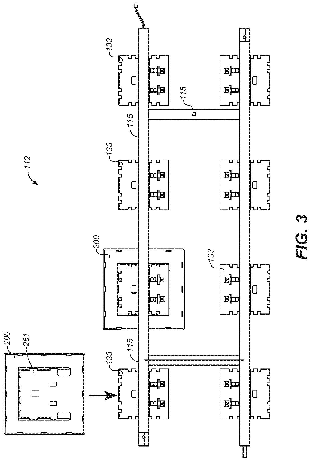
[0006]More particularly, the invention involves a loadable cassette for releasably holding both a planar light source, such as an OLED panel, and a driver board for the light source so as to prevent thermal contact between these components. The cassette allows for easy insertion of a driver board and planar light source, while also allowing for wired connections within the cassette and to external wiring for the luminaire or lighting system to which the cassette is attached.
[0007]The cassette includes a low profile framing structure that can releasably retain the planar light source in a first plane and the driver board in a second plane substantially parallel to the first plane. In one aspect of the invention, there is sufficient distance between the first and second planes such that, when the light source and driver board are releasably retained within the framing structure, no portion of the driver board is in substantial contact, and preferably no direct contact, with the light source.

Problems solved by technology

The difficulty with this approach is that the panel drivers produce heat, which detrimentally affects the operation of the OLEDs.
More generally, employing OLED's as the light source of choice presents challenges for lighting designers.
Unlike conventional light sources, such as incandescent bulbs or fluorescent tubes that can easily be plugged into compatible lamp sockets mounted in a luminaire, flat panel light sources are relatively difficult to integrate into the structural environment of a luminaire or lighting system, and are relatively difficult to remove and replace.
However, while facilitating the attachment of OLED panels, the disclosed cassette structure does not contemplate the use of, or provide for accommodating a local driver for the OLED panel held in the cassette, much less addressing the problem of heat transfer between the OLED panel and a panel driver used with an OLED panel.

Method used


Image

  • Cassette for holding a planar light source with a thermally isolated driver board
  • Cassette for holding a planar light source with a thermally isolated driver board
  • Cassette for holding a planar light source with a thermally isolated driver board

Examples


Embodiment Construction

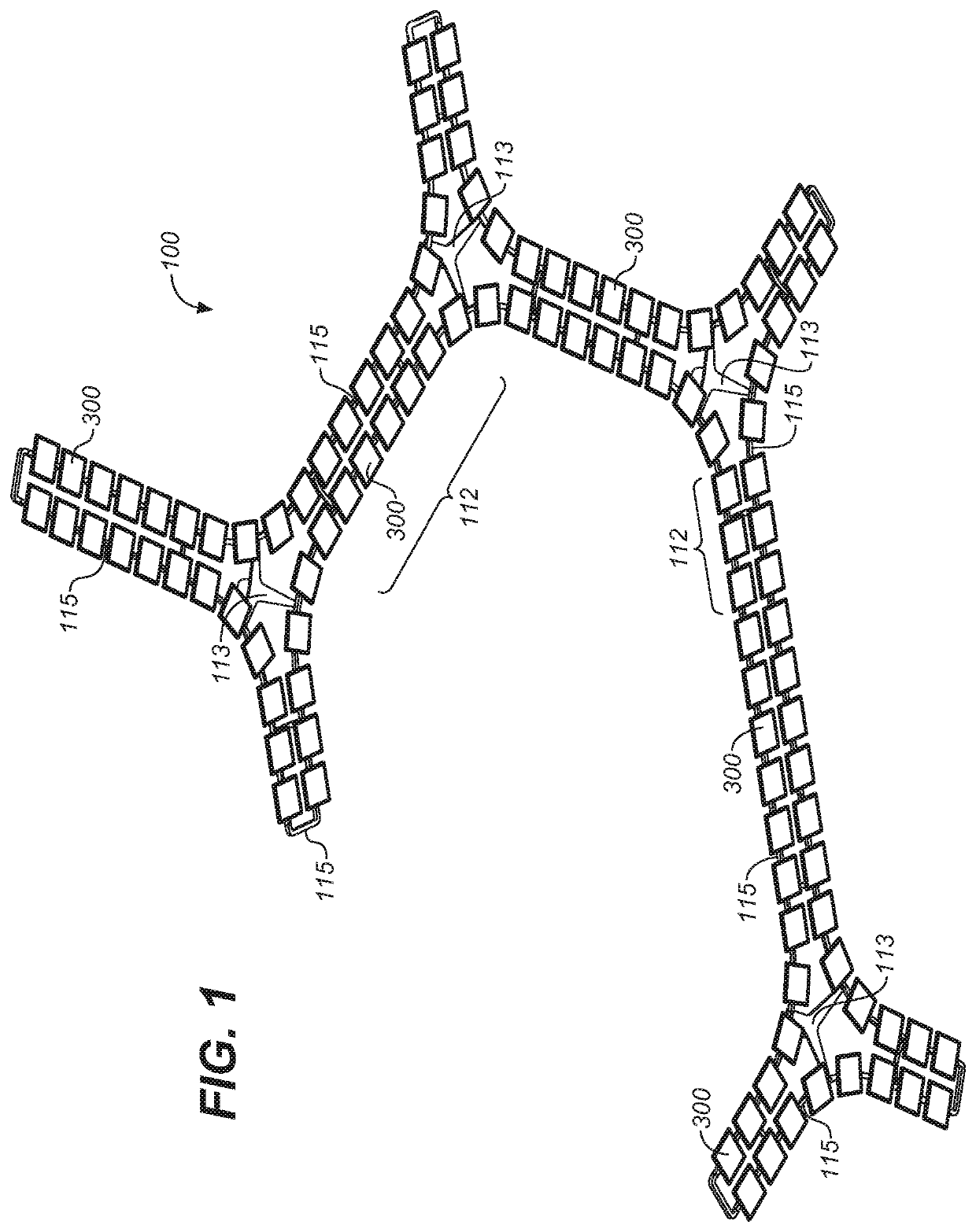
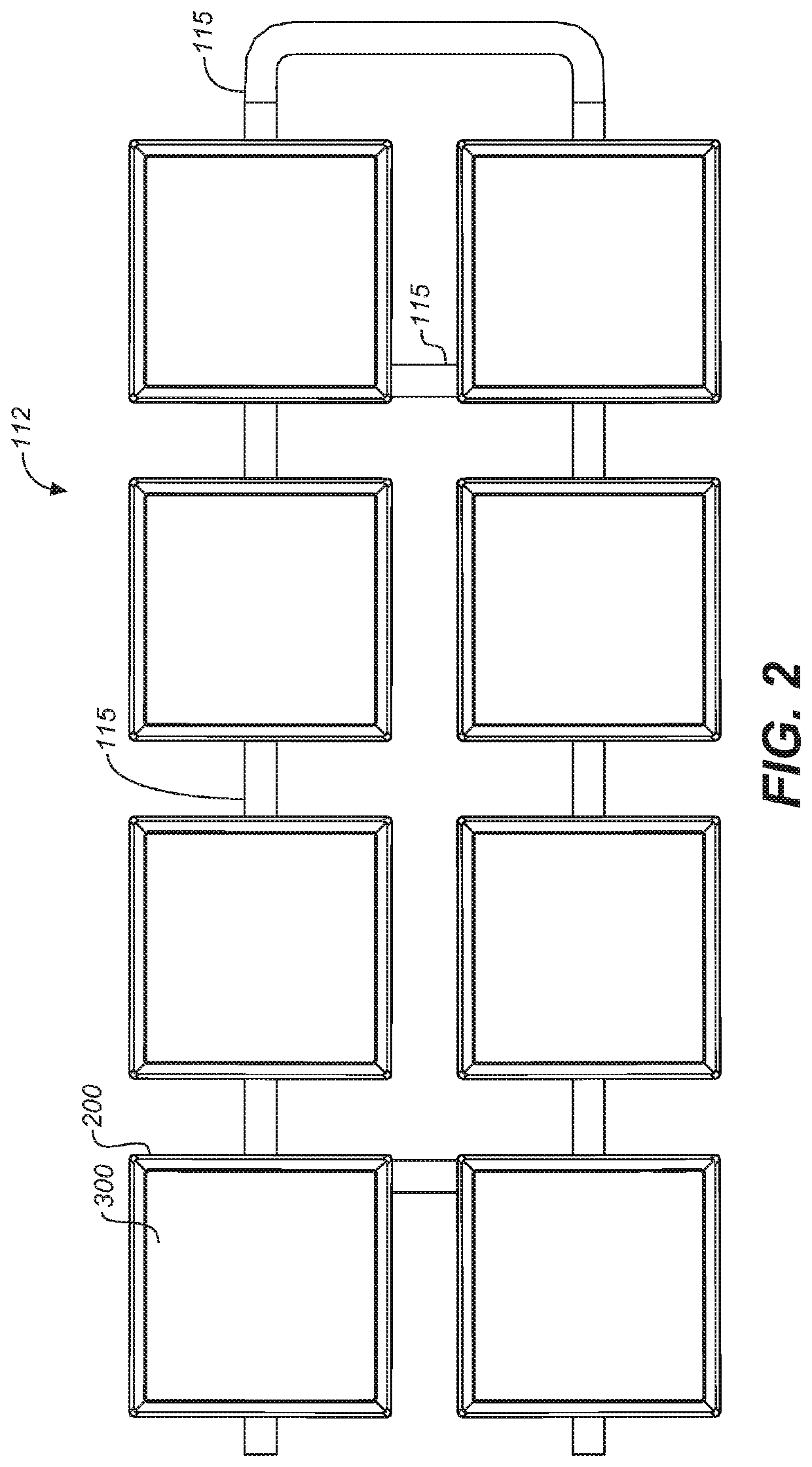
[0033]Referring now to the drawings, FIG. 1 shows a configurable, two-dimensional lighting system 100 comprising a large number of flat panel light sources 300. The lighting system is formed of a plurality of low profile, radial hubs 113 that can be attached to or suspended from a ceiling surface and a plurality of connector rails 115 that connect to the suspended hubs. The hubs are interconnected in a manner that allows the lighting system to propagate out into a two dimensional plane along a ceiling surface. Additional hubs and connector rails can be used to expand the lighting system in multiple directions within the two dimensional plane.

[0034]The planar light sources 300 are connected to the hubs and connector rails of the lighting system to form a large array of light sources, with the hubs and connector rails providing wireways for electrical wiring, or other suitable conductors, for bringing power to the light sources. Preferably, flat panel light sources are OLED panels, bu...


PUM

PropertyMeasurementUnit
distanceaaaaaaaaaa
profile framing structureaaaaaaaaaa
structure retentionaaaaaaaaaa

Abstract

A loadable cassette holds a planar light source, such as a flat OLED panel, along with a companion driver board in a manner that allows both the light source and driver board to be operatively and replaceably connected to a luminaire or lighting system. The cassette maintains an air gap between the light source and driver board so as to prevent heat produced by the driver board from damaging the light source.

Description

GOVERNMENT RIGHTS[0001]This invention was made with Government support under U.S. Department of Energy Award No. DE-EE0007073. The Government has certain rights in the invention.BACKGROUND OF INVENTION[0002]The present invention generally relates to lighting systems that use planar light sources such as Organic Light Emitting Diodes (OLEDs), and more particularly relates to a means for operatively attaching planar light sources to such lighting systems.[0003]OLED lighting systems exist that are comprised of a number of, and often a large number of, OLED panels. Individual OLED panels within the lighting system can be provided with their own microprocessor control unit, sometimes referred to as a “driver,” which allows an OLED panel to be addressed by a system control unit for monitoring and controlling the panel. Heretofore, the approach to providing local panel drivers for the OLED panels of an OLED lighting system has been to bond the drivers directly to the back of the OLED panel...

Claims


Application Information

Patent Timeline
Patent Type & Authority Patents(United States)
IPC IPC(8): F21S2/00F21V15/01F21V19/00F21V21/34F21V23/06F21V23/00F21Y115/15
CPCF21V21/34F21V23/006F21V23/06F21S2/00Y02B20/36F21V19/001F21Y2115/15F21V15/01Y02B20/30
Inventor LU, MIN-HAO MICHAELWICKUS, JONATHON
Owner ABL IP HLDG
Learn More