This helps you quickly interpret patents by identifying the three key elements:
Problems solved by technology
Method used
Benefits of technology
[0026] a fourth supporting apparatus secured on said first movable plate for supporting said sec
Problems solved by technology
In order to project a picture of proper position onto the screen, the projector must be adjusted to the proper relative position with respect to the screen, and considerable time and effort are therefore required to position the projector.
In such a case, however, since the angle between the projection lens and the screen surface changes, the p
Method used
Image
Click on the blue label to locate the original text in one second.
Reading with bidirectional positioning of images and text.
Examples
first embodiment
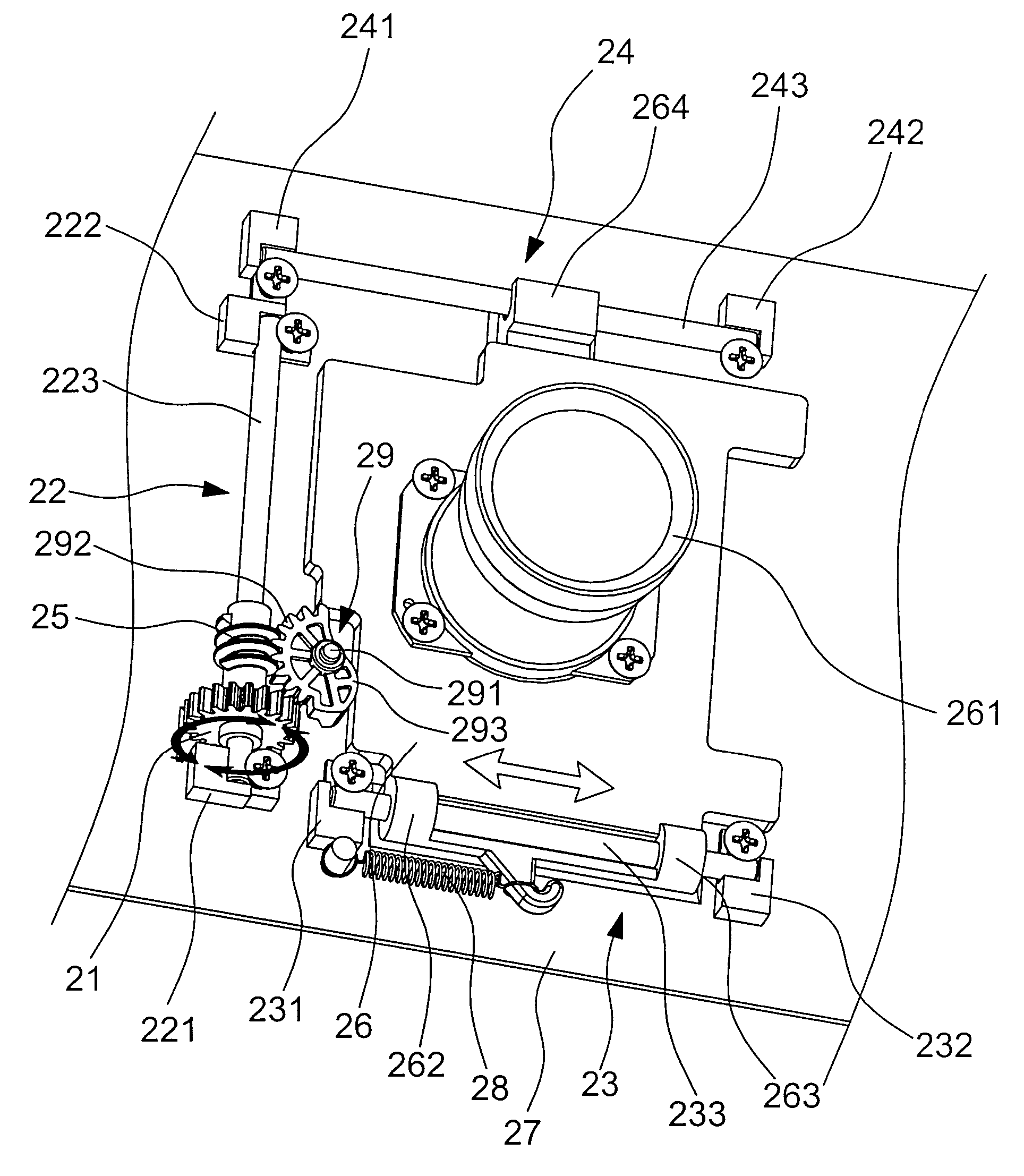
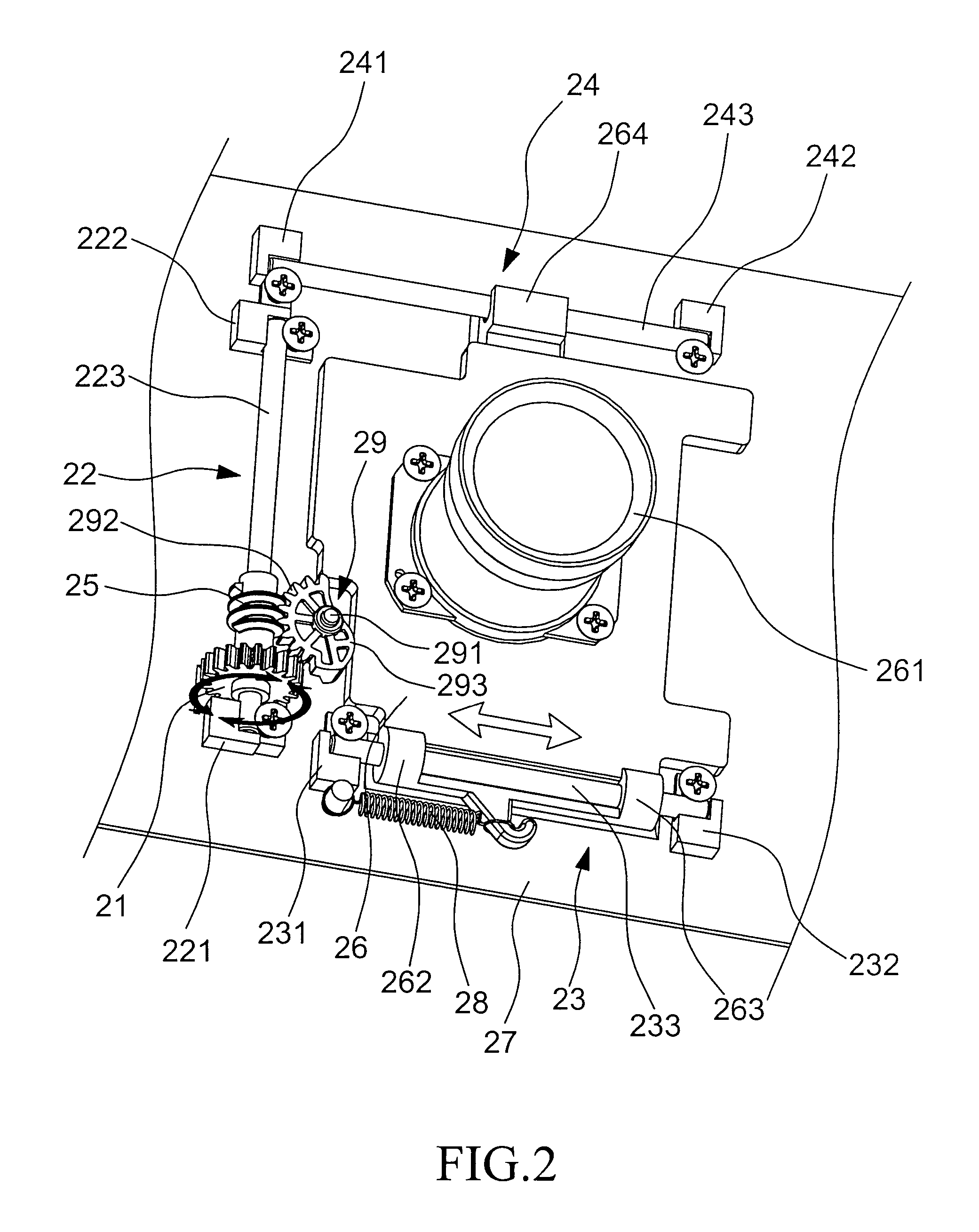
[0033] Referring to FIG. 2, a perspective view of the projection lens shifting mechanism according to the present invention is shown. The projection lens shifting mechanism 2 comprises: a driving apparatus (for example, a driving wheel 21), a first supporting apparatus 22, a transmitting apparatus, a movable plate 26, a second supporting apparatus 23, a third supporting apparatus 24 and an elastic member 28.
[0034] The driving wheel 21 has a central axis that is parallel to the surface of base plate 27, and rotates when an external force is applied thereon.
[0035] The first supporting apparatus 22 comprises two pedestals 221, 222 and a fixed bar 223. The pedestals 221, 222 are secured on base plate 27. The fixed bar 223 is secured to the pedestals 221, 222, so that the central axis of the fixed bar 223 is parallel to the surface of base plate 27 and the light valve of the projector.
[0036] The transmitting apparatus is driven by said driving wheel 21 for changing the direction of the...
third embodiment
[0044] Referring to FIG. 4, a perspective view of the projection lens shifting mechanism according to the present invention is shown. This embodiment is a combination of two projection lens shifting mechanisms of FIG. 2. The projection lens shifting mechanism 4 of this embodiment comprises: a first driving apparatus (for example, a first driving wheel 41), a first supporting apparatus 42, a first transmitting apparatus, a first movable plate 46, a second supporting apparatus 43, a second driving apparatus (for example, a second driving wheel 51), a third supporting apparatus 44, a second transmitting apparatus, a second movable plate 56 that is above the first movable plate 46, a fourth supporting apparatus 52, a first elastic member 48 and a second elastic member 58.
[0045] The first driving wheel 41 has a central axis that is parallel to the surface of base plate 47, and rotates when an external force is applied thereon.
[0046] The first supporting apparatus 42 comprises two pedest...
PUM
Abstract
The present invention relates to a projection lens shifting mechanism having: a driving apparatus, a first supporting apparatus, a transmitting apparatus, a movable plate and a second supporting apparatus. The transmitting apparatus is driven by the driving apparatus for changing a direction of the torque transmitted by the driving apparatus. The movable plate, on which a projection lens is mounted, is in contact with the transmitting apparatus to be driven by the transmitting apparatus to translate in a perpendicular direction with respect to the central axis of the driving apparatus, whereby providing a user-friendly interface, that is, when it is operated manually, a direction that the user applies force against the driving apparatus is consistent with that the movable plate translates. Furthermore, after two above mechanisms are combined, the projection lens can be positioned in any position of a two-dimensional plane.
Description
BACKGROUND OF THE INVENTION [0001] 1. Field of the Invention [0002] The present invention relates to a projection lens shifting mechanism, and more particularly a projection lens shifting mechanism that enables two-dimensional adjustment of a projection lens. [0003] 2. Description of the Related Art [0004] Conventionally, the projection lens of a projector is fixed, and the position of the picture projected onto the screen is therefore determined by the relative position or angle of the screen and projector. In order to project a picture of proper position onto the screen, the projector must be adjusted to the proper relative position with respect to the screen, and considerable time and effort are therefore required to position the projector. [0005] When the projector is set up, and it is desired to shift the position of the picture on the screen still higher, the projection direction is shifted upward by means of a height adjustment mechanism attached to the forward legs of the pr...
Claims
Application Information
Patent Timeline
Application Date:The date an application was filed.
Publication Date:The date a patent or application was officially published.
First Publication Date:The earliest publication date of a patent with the same application number.
Issue Date:Publication date of the patent grant document.
PCT Entry Date:The Entry date of PCT National Phase.
Estimated Expiry Date:The statutory expiry date of a patent right according to the Patent Law, and it is the longest term of protection that the patent right can achieve without the termination of the patent right due to other reasons(Term extension factor has been taken into account ).
Invalid Date:Actual expiry date is based on effective date or publication date of legal transaction data of invalid patent.