
Intershaft Seal Assembly with Pressure-Balanced Translatable Carrier

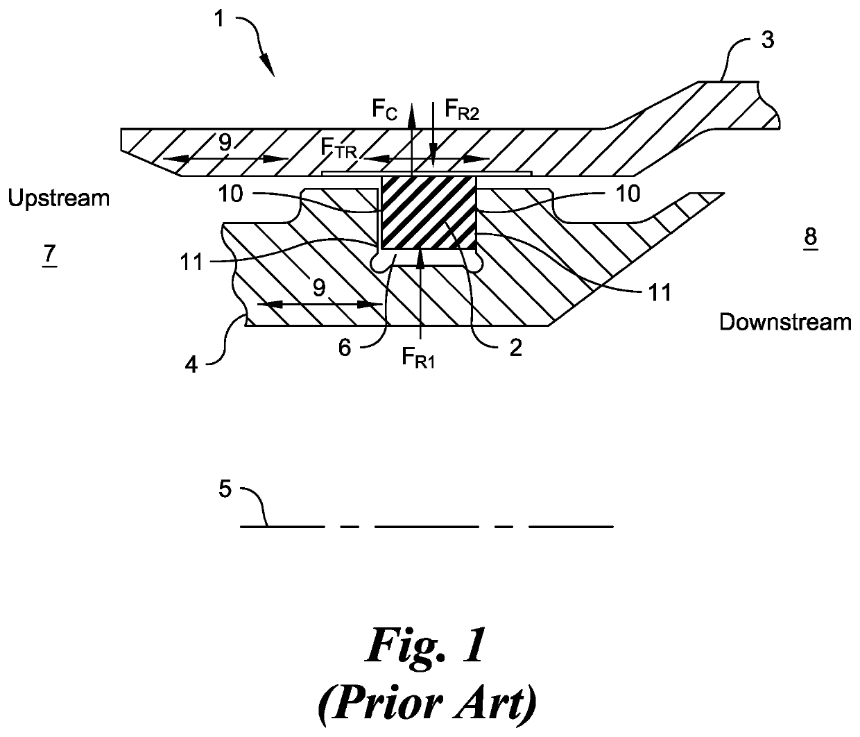
a technology of intershaft seals and carrier plates, which is applied in the direction of engine seals, engine components, machines/engines, etc., can solve the problems of higher operating costs and more frequent maintenance of turbine engines over the lifespan of the engine, and achieve the effect of reducing frictional face wear

Active Publication Date: 2022-05-05
STEIN SEAL
View PDF6 Cites 0 Cited by
  • Summary
  • Abstract
  • Description
  • Claims
  • Application Information

AI Technical Summary

Benefits of technology

The patent describes an intershaft sealing arrangement for turbine engines which helps prevent friction and heating along a sealing ring. The arrangement includes a primary sealing ring and one or more secondary sealing rings that allow a carrier to move relative to an inner structure. The design reduces wear and heating along the sealing ring and inner structure, minimizing contact between them. This results in a more efficient and reliable sealing arrangement for turbine engines.

Problems solved by technology

The end results may include more frequent maintenance and higher operating costs over the lifespan of a turbine engine.

Method used


Image

  • Intershaft Seal Assembly with Pressure-Balanced Translatable Carrier
  • Intershaft Seal Assembly with Pressure-Balanced Translatable Carrier
  • Intershaft Seal Assembly with Pressure-Balanced Translatable Carrier

Examples


Embodiment Construction

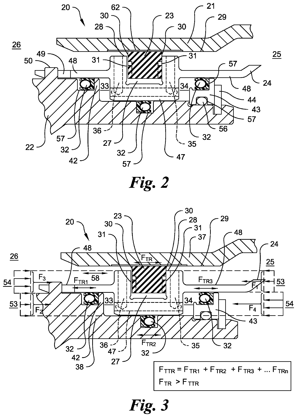
[0072]Reference will now be made in detail to several embodiments of the disclosure that are illustrated in the accompanying drawings. Wherever possible, same or similar reference numerals may be used in the drawings and the description to refer to the same or like parts.

[0073]While features of various embodiments are separately described herein, it is understood that such features may be combinable to form other additional embodiments.

[0074]One or more components described herein may be manufactured via methods, processes, and techniques understood in the art, including, but not limited to, machining, molding, forming, and three-dimensional printing.

[0075]The drawing figures are not necessarily drawn to scale, but instead are drawn to provide a better understanding of the components thereof, and are not intended to be limiting in scope, but to provide exemplary illustrations.

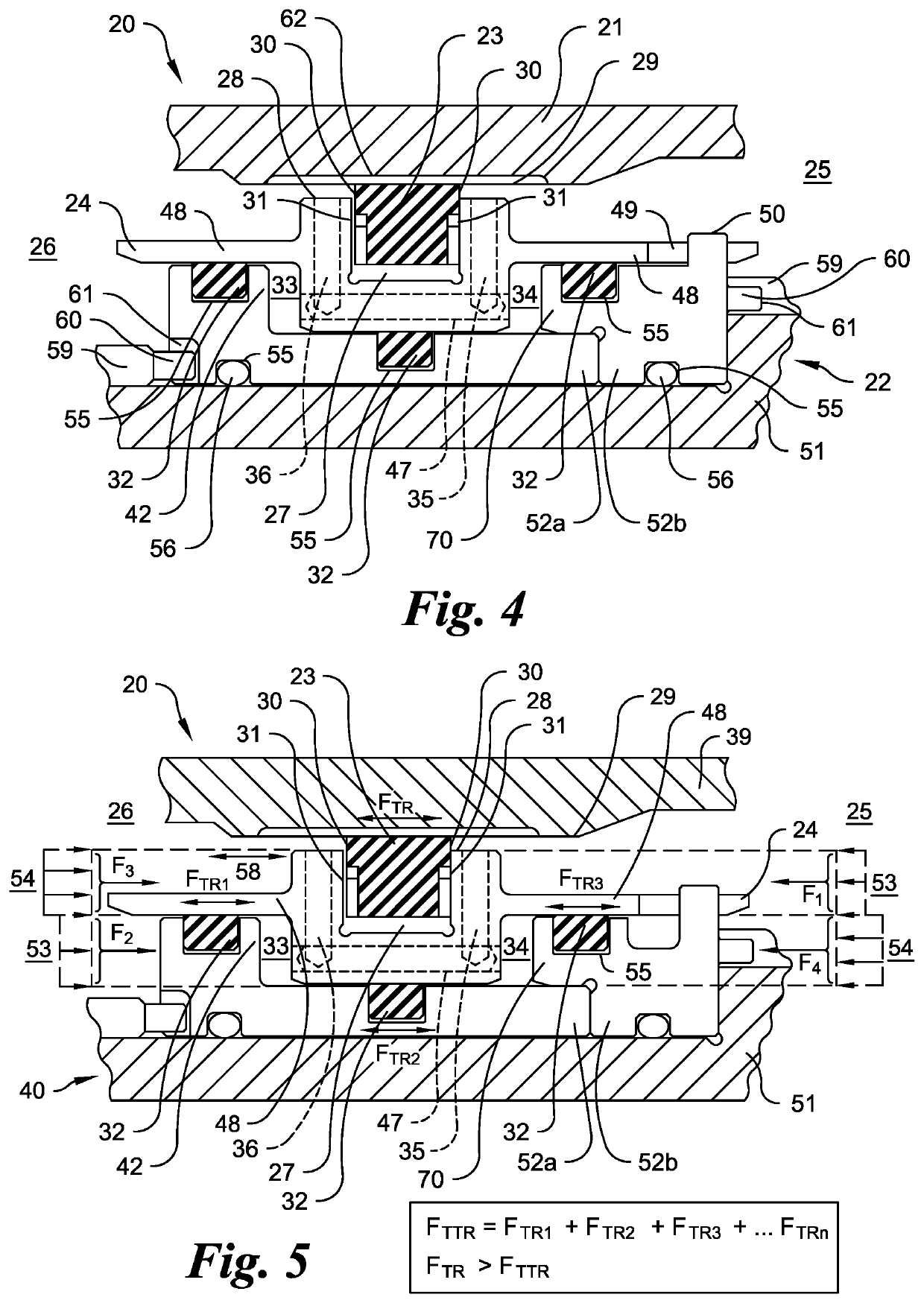
[0076]Referring now to FIG. 2, the intershaft seal assembly 20 is sealingly positioned between a rotatable o...


PUM


Abstract

An intershaft seal assembly for use between a rotatable outer structure and an inner structure within a turbine engine is presented. The assembly includes a primary sealing ring, a translatable carrier, a secondary sealing ring(s), a lower-pressure chamber, a higher-pressure chamber, a first channel(s), and a second channel(s). The primary ring is disposed within and extends from a circumferential groove about the carrier so as to sealingly engage the rotatable outer structure. The primary ring rotates within the groove and with the rotatable outer structure. Each secondary ring is interposed between the carrier and the inner structure. The carrier slidingly contacts the secondary ring(s). The lower-pressure chamber is generally defined by the carrier and the inner structure adjacent to a higher-pressure side. The higher-pressure chamber is generally defined by the carrier and the inner structure adjacent to a lower-pressure side. Each first channel traverses the carrier so that a gas from the lower-pressure side may enter the lower-pressure chamber. Each second channel traverses the carrier so that a gas from the higher-pressure side may enter the higher-pressure chamber. The sum of the translation-resistant forces (FTTR) encountered by the carrier is less than the translation-resistance force (FTR) encountered by the primary seal ring.

Description

CROSS REFERENCE TO RELATED APPLICATIONS[0001]This application is a National Phase of PCT Application No. PCT / US2020 / 042746 filed Jul. 20, 2020 entitled Intershaft Seal Assembly with Pressure-Balanced Translatable Carrier which is incorporated in its entirety herein by reference thereto.GOVERNMENT SPONSORED RESEARCH AND DEVELOPMENT[0002]None.BACKGROUND OF THE DISCLOSURE1. Field[0003]The disclosure generally relates to sealing within a turbine engine and more particularly is concerned, for example, with an intershaft seal assembly including a ring disposed within a groove about a translatable carrier between a rotatable outer structure and an inner structure, the latter either fixed or rotatable, wherein the translatable carrier is pressure balanced between a higher-pressure side and a lower-pressure side and the translatable carrier contacts at least one secondary sealing ring which permits the carrier to axially translate when in contact with the sealing ring.2. Background Art[0004]...

Claims


Application Information

Patent Timeline
Patent Type & Authority Applications(United States)
IPC IPC(8): F02C7/28F16J15/00F16J15/3244
CPCF02C7/28F16J15/006F05D2220/32F05D2240/55F16J15/3244F01D11/00F05D2240/60F16J15/441F16J15/56F16J15/3252
Inventor GARRISON, GLENN M.
Owner STEIN SEAL
Learn More