
Method for determining wear of a friction plate

a friction plate and friction lining technology, applied in the direction of machine part testing, computation using non-denominational number representation, complex mathematical operations, etc., can solve the problem of too complex and expensive types of wear determination, too complicated and expensive for merely determining the thickness of the clutch lining, etc., to prevent the depreciation of function due to a worn friction lining, the effect of reliably determining friction wear in a time interval

Inactive Publication Date: 2013-12-03
SCHAEFFLER TECH AG & CO KG
View PDF9 Cites 3 Cited by
  • Summary
  • Abstract
  • Description
  • Claims
  • Application Information

AI Technical Summary

Benefits of technology

[0011]The invention is therefore based on the object of providing a method named at the beginning, whereby friction wear in a time interval can be determined reliably and with only a little effort, so that a depreciation of function due to a worn friction lining can be prevented in a timely manner.
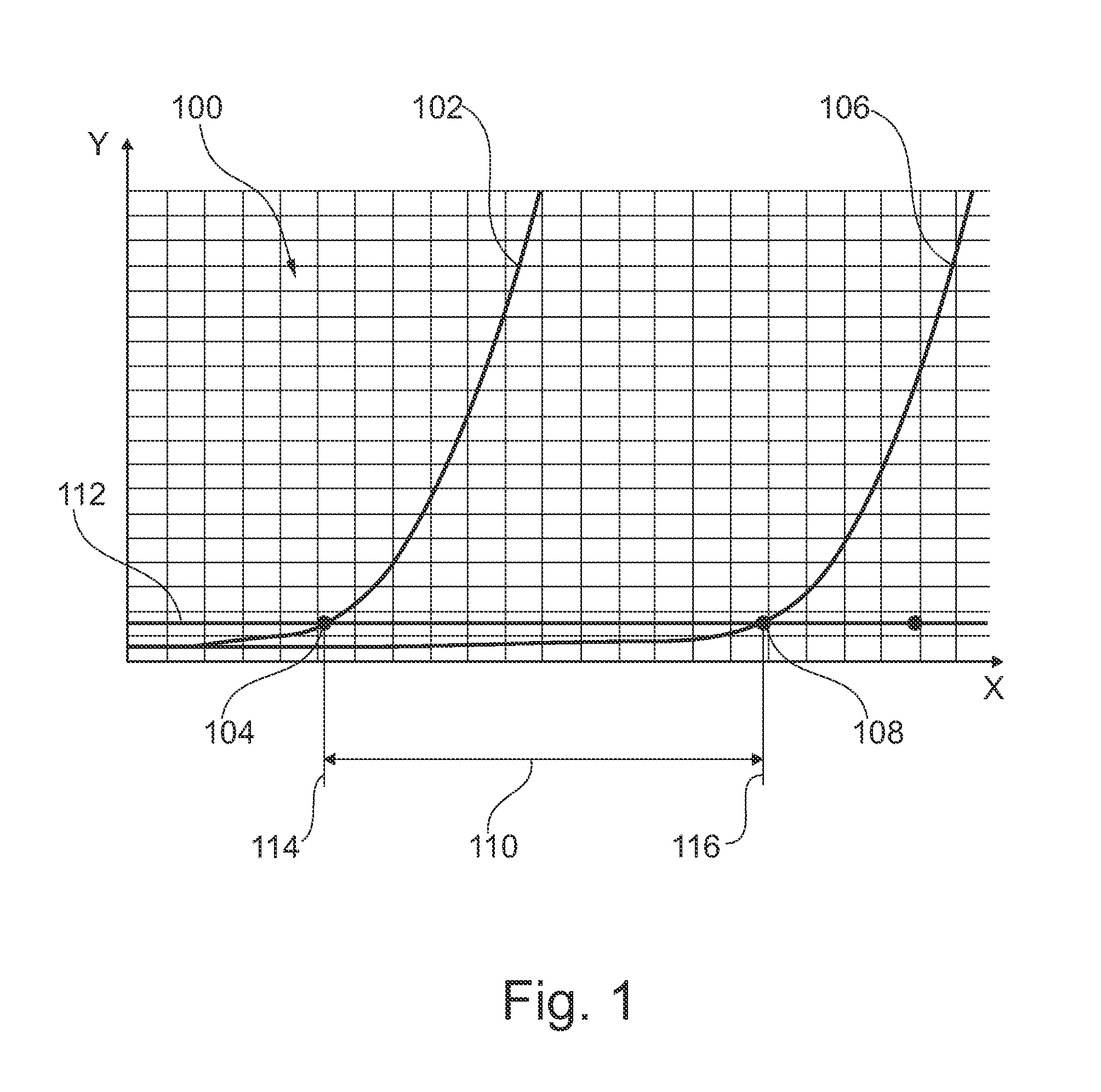
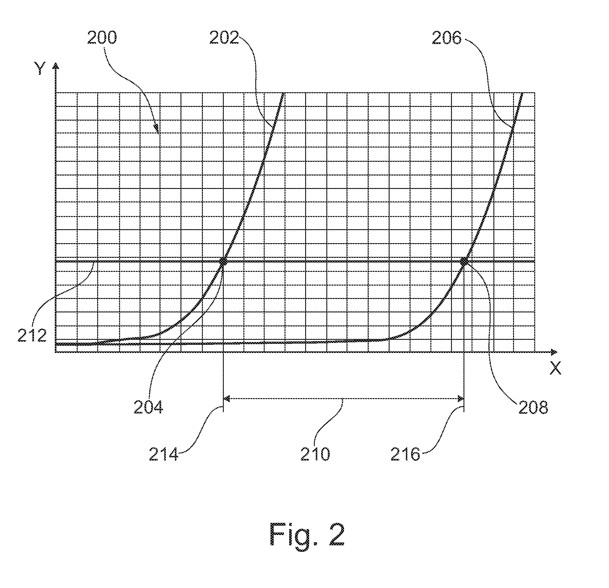
[0012]The object is fulfilled by a method having the steps of first determining and storing an earlier clutch actuation distance at a predetermined clutch slip and a predetermined clutch torque in an earlier friction lining test point, later again determining a later clutch actuation distance at the predetermined clutch slip and the predetermined clutch torque at a later friction lining test point, subsequently comparing the earlier clutch actuation distance and the later clutch actuation distance with each other and determining a differential value, and then determining friction lining wear taking the differential value into account. This makes it possible to reliably determine friction lining wear and with high precision, without need of disassembly and visual inspection.

Problems solved by technology

In the case of increased wear and early erosion of the lining, the point at which the limits of the lining has been reached is not noticed until the lining has completely worn down, for example acoustically by a scraping rivet of the clutch plate or by lack of torque capacity of the clutch.
As a rule, early diagnosis is only possible by means of disassembly and visual inspection, and this is too complicated and too expensive for merely determining the thickness of the clutch lining.
However, these types of wear determination are either very complex, or do not satisfy elevated demands for precision.

Method used


Image

  • Method for determining wear of a friction plate
  • Method for determining wear of a friction plate
  • Method for determining wear of a friction plate

Examples


Embodiment Construction

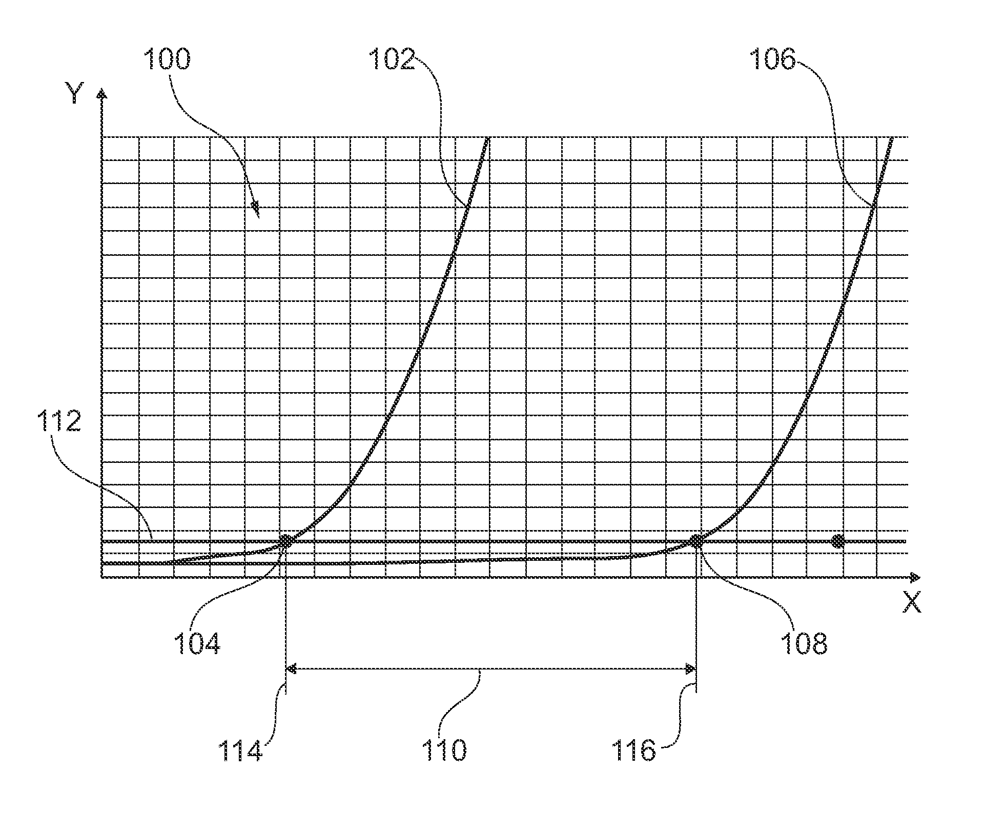
[0025]Diagram 100 shown in FIG. 1 pertains to an automatically operated friction clutch of a motor vehicle driven by an internal combustion engine. The friction clutch is situated between the combustion engine and a transmission, and has an input part on the combustion engine side which includes a housing or cover, a pressure plate and an opposing pressure plate. The cover is rigidly connected to the opposing pressure plate, for example by riveting; the connection of the pressure plate is rotationally fixed but axially movable. On the transmission side, the clutch has an output part which includes at least one clutch plate with friction linings.

[0026]However, the friction clutch may also be a dual clutch having on the combustion engine side an input part that includes a housing or cover, a pressure plate, an intermediate pressure plate and an opposing pressure plate. On the transmission side the dual clutch has a first and a second output part, each of which includes at least one cl...


PUM


Abstract

Method for determining wear of a friction plate of an automatically actuated friction clutch, particularly in a motor vehicle driven by an internal combustion engine, wherein initially at a prescribed clutch slip and a prescribed clutch torque in an earlier friction lining test point an earlier clutch actuation travel is determined and stored, later again at the prescribed clutch slip and the prescribed clutch torque in a later friction lining test point a later clutch actuation travel is determined, thereafter the earlier clutch actuation travel and the later clutch actuation travel are compared to each other and a differential value is determined, and thereafter a friction lining wear is determined using the differential value, in order to reliably determine friction lining wear in a time interval and with only little effort, so that a depreciation of function due to a worn friction lining can be prevented in a timely manner.

Description

CROSS-REFERENCE TO RELATED APPLICATIONS[0001]This application is filed under 35 U.S.C. §120 and §365(c) as a continuation of International Patent Application No. PCT / DE2011 / 001570 filed Aug. 10, 2011, which application claims priority from German Patent Application No. 10 2010 044 882.6 filed Sep. 9, 2010, which applications are incorporated herein by reference in their entirety.TECHNICAL FIELD[0002]The invention relates to a method for determining wear of a friction plate of an automatically actuated friction clutch, in particular in a motor vehicle driven by an internal combustion engine.BACKGROUND[0003]Within the framework of the present application, “friction clutch” is understood to mean in particular a friction clutch which is situated in the drivetrain of motor vehicles driven by an internal combustion engine, between the combustion engine and a transmission, which enables driving off as well as changing the gear ratio, and which for technical reasons is only possible when th...

Claims


Application Information

Patent Timeline
Patent Type & Authority Patents(United States)
IPC IPC(8): G01M17/00
CPCF16D48/06G01M13/022G01M13/00F16D2500/3026F16D2500/30406F16D2500/30421F16D2500/5023F16D2500/50236F16D2500/50251
Inventor KNEISSLER, MARKUSSCHIEFERDECKER, PATRICK
Owner SCHAEFFLER TECH AG & CO KG
Learn More