
Device for supplying secondary air in a gas turbine engine

a gas turbine engine and secondary air technology, applied in the direction of engines, efficient propulsion technologies, mechanical devices, etc., can solve the problems of reducing the overall efficiency of the engine, preventing adequate cooling, wasting useful energy, etc., and achieve the effect of increasing temperature and pressur

Active Publication Date: 2005-06-23
HONDA MOTOR CO LTD
View PDF1 Cites 38 Cited by
  • Summary
  • Abstract
  • Description
  • Claims
  • Application Information

AI Technical Summary

Benefits of technology

[0013] A second object of the present invention is to provide a device for supplying secondary air in a gas turbine engine that demonstrates a high efficiency at a normal operating rotational speed and can avoid an excessive seal pressure (flow rate) while ensuring a suitable seal pressure even at an idle rotational speed.
[0014] A third object of the present invention is to provide a device for supplying secondary air in a gas turbine engine that can derive seal air of a desired quality while minimizing power loss due to the derivation of the seal air.
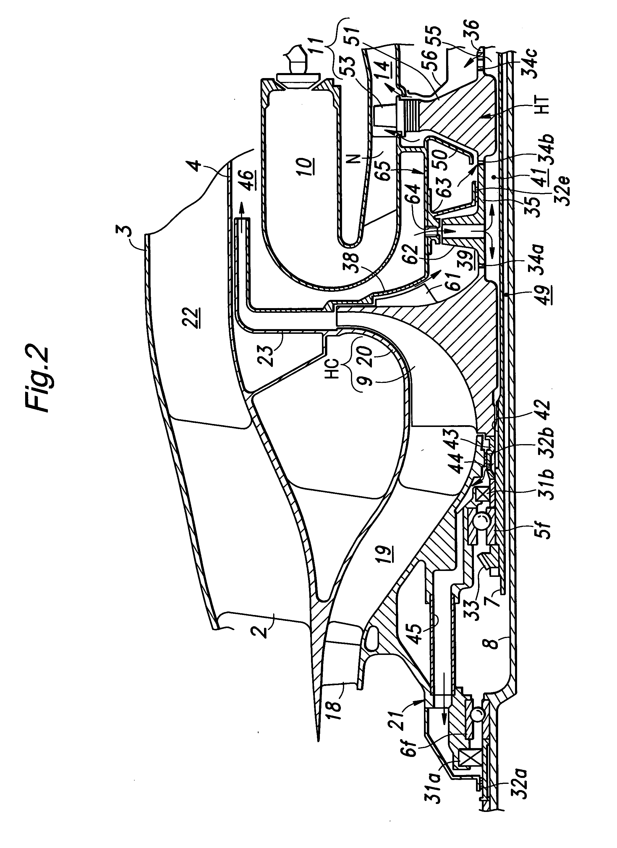
[0015] The present invention can achieve at least some of the foregoing object by providing a device for supplying secondary air in a gas turbine engine, comprising: an inner shaft connected to a low pressure compressor and a low pressure turbine; an outer shaft, coaxially disposed with respect to the inner shaft, connected to a high pressure compressor and a high pressure turbine; at least a pair of bearing boxes which are spaced from each other in an axial direction each accommodating a bearing for supporting an end of the inner or outer shaft; a seal air introduction passage for introducing a part of high pressure air drawn from the high pressure compressor into a seal section provided in each of the bearing boxes; and a high pressure air introduction turbine provided in the seal air introduction passage and attached to a part attached to the outer shaft in a rotationally fast manner.
[0016] Owing to the use of the high pressure air introduction turbine as a means for providing a seal pressure to the seal section of each bearing box, work is extracted from the seal air and cooling air, typically derived from a high pressure chamber defined downstream of a diffuser connected to a downstream end of the high pressure compressor and having a high temperature and high pressure by taking advantage of the action of the turbine at the normal operating rotational speed so that an excessive rise in the seal pressure at the normal rotational speed can be avoided and, at the same time, the supplied air having a high pressure and high temperature can be reduced in temperature thereby avoiding an excessive rise in the temperature of the lubricating oil for the bearing.
[0019] The seal air introduction passage may comprise a radial air passage provided in a part attached to the outer shaft in a rotationally fast manner so as to permit a flow of seal air from an inner peripheral part thereof to an outer peripheral part thereof, and an outlet air flow from the radial air passage recedes with respect to a rotational direction of the outer shaft. Thereby, the radial air passage is prevented from functioning as a compressor with respect to the air flow that passes through the radial air passage in a radially outward direction. Thereby, the air is prevented from receiving work as it passes through the radial air passage and thereby being increased in temperature and pressure.

Problems solved by technology

However, the gas turbine engines that supply air for cooling and sealing as described above have the following problems.
(1) Because the high-pressure, high-temperature gas (secondary air) produced by the compressor is used for purposes other than providing a thrust, the overall efficiency of the engine is reduced.
(2) Because the pressure of the air compressed by the compressor is excessively high, the air needs to be reduced in pressure by using such means as an orifice, and this means a waste of usefully energy.
This prevents adequate cooling of the lubricating oil, undesirably heats such components as the casing typically made of aluminum alloy and gears typically made of steel, and causes premature degradation of the lubricating oil.
(4) High-temperature compressed air is not effective in cooling a turbine so that a correspondingly large amount of cooling air is required to be bled.
(5) When an orifice controls the pressure and flow rate of the seal air so as to ensure a required seal pressure at an idle rotational speed, the pressure of the seal air tends to be excessive at a normal operational rotational speed, and a large loss is incurred owing to an excessive bleeding.
However, in case of small engines, in particular those using a centrifugal compressor, each stage compresses air by such a large factor that it is difficult to bleed air that has an appropriate pressure and temperature.

Method used


Image

  • Device for supplying secondary air in a gas turbine engine
  • Device for supplying secondary air in a gas turbine engine
  • Device for supplying secondary air in a gas turbine engine

Examples


Embodiment Construction

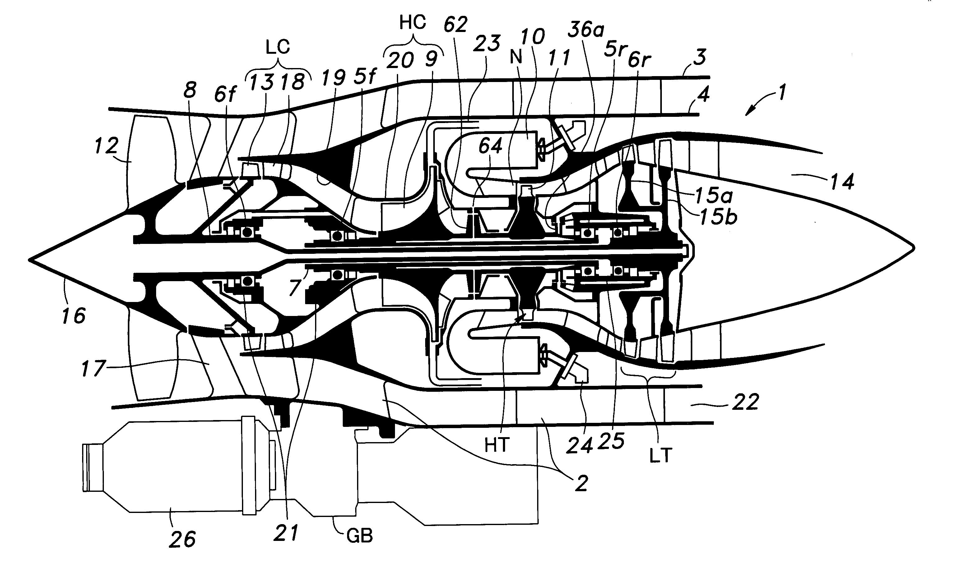
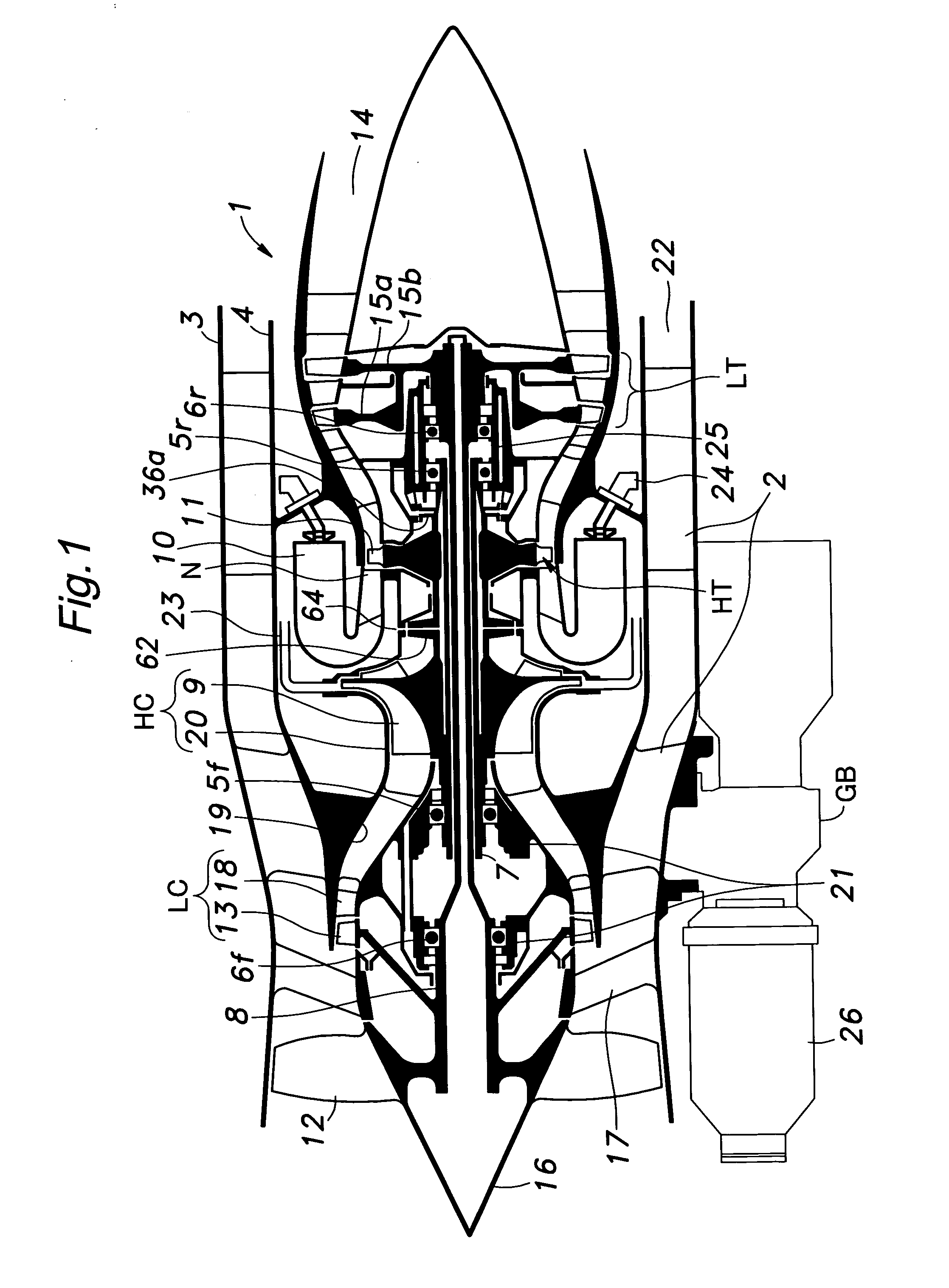
[0030]FIG. 1 is a schematic view of a multiple shaft bypass jet engine embodying the present invention. This engine 1 comprises an outer casing 3 and an inner casing 4 consisting of coaxially arranged cylindrical members joined to each other by struts 2, and an outer shaft 7 and an inner shaft 8 consisting of coaxially arranged hollow shafts centrally supported in the casings by independent bearings 5f, 5r, 6f and 6r.

[0031] The outer shaft 7 has a front end (left end in the drawing) integrally carrying an impeller wheel 9 of a high pressure centrifugal compressor HC, and a rear end (right end in the drawing) integrally carrying a high pressure turbine wheel 11 of a high pressure turbine HT provided adjacent to nozzles N of counter-flow combustion chambers 10.

[0032] The inner shaft 8 has a front end integrally carrying a front fan 12 and a compressor wheel 13 supporting rotor vanes for a low pressure axial flow compressor LC immediately behind the front fan 12, and a rear end integ...


PUM


Abstract

In a device for supplying secondary air in a gas turbine engine provided with an inner shaft (8) supporting a low pressure compressor and a low pressure turbine and a hollow outer shaft (7) coaxially nested with the inner shaft and supporting a high pressure compressor and a high pressure turbine, a seal air introduction passage (41, 45, 48) for introducing a part of high pressure air drawn from the high pressure compressor into a seal section provided in each of the bearing boxes is provided with a high pressure air introduction turbine (62) attached to the outer shaft in a rotationally fast manner. Owing to the use of the high pressure air introduction turbine, work is extracted from the seal air and cooling air derived from the supplied air and having a high temperature and high pressure air so that an excessive rise in the seal pressure at the normal rotational speed can be avoided and, at the same time, the supplied air can be reduced in temperature thereby avoiding an excessive rise in the temperature of the lubricating oil for the bearing.

Description

TECHNICAL FIELD [0001] The present invention relates to a device for supplying secondary air in a gas turbine engine. BACKGROUND OF THE INVENTION [0002] In a certain conventional gas turbine engine, an inner shaft supporting a low pressure compressor and a low pressure turbine and an outer shaft supporting a high pressure compressor and a high pressure turbine typically consist of hollow shafts which are coaxially nested with each other. Such a gas turbine engine is disclosed in the U.S. Pat. No. 5,862,666. According to the conventional gas turbine engine disclosed in this U.S. patent, the outer and inner shafts are supported by separate bearings at their front and rear ends, and each bearing is lubricated by a forced lubrication system which blows lubricating oil fed by a pump to the bearing. [0003] In such a forced lubricating system, to positively prevent the lubricating oil from leaking out of the bearing boxes provided in the front and rear ends of the outer and inner shafts, h...

Claims


Application Information

Patent Timeline
Patent Type & Authority Applications(United States)
IPC IPC(8): F01D3/02F01D5/08F01D11/04F01D25/12F01D25/18F02C7/06F02C7/18F02C7/28F16C33/76
CPCF01D3/02F01D11/04F01D25/125Y02T50/675F02C7/06F02C7/28F16C33/76F01D25/183F16C2360/23Y02T50/60F02C7/00F16C33/66
Inventor FUKUTANI, MASAYUKIWARAGAI, ATSUKUNINODA, ETSUO
Owner HONDA MOTOR CO LTD
Learn More