Gate valve

a gate valve and valve body technology, applied in the direction of valve operating means/releasing devices, mechanical equipment, vacuum evaporation coating, etc., to achieve the effect of reliable sealing and tightness

Inactive Publication Date: 2001-10-16
APPLIED MATERIALS GMBH & CO KG
View PDF10 Cites 44 Cited by
  • Summary
  • Abstract
  • Description
  • Claims
  • Application Information

AI Technical Summary

Benefits of technology

to overcome the problem of constructing a gate valve of the type described herein so that, with the least possib

Problems solved by technology

Since the passage openings, however, can be several meters wide, in the manufacturing of glass, for example, the sealing of such flaps or sliders causes difficulties.
With flaps there is the problem that their swivel axis must run precisely

Method used


Image

  • Gate valve
  • Gate valve
  • Gate valve

Examples


Embodiment Construction

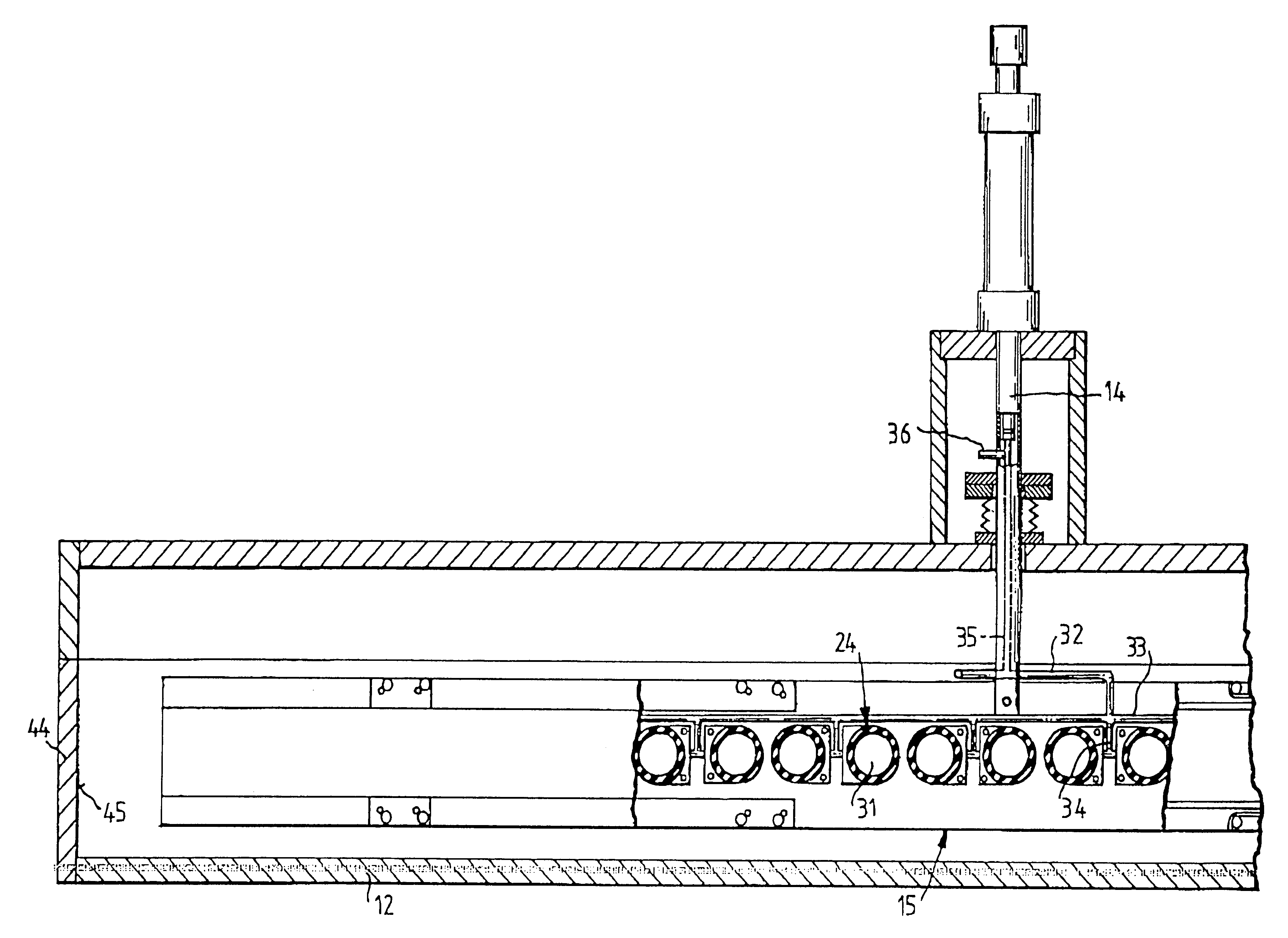
An advantageous refinement of the invention is to be found in that the slider has a middle basic element on which the valve plates are held with leaf springs in a prestressed position with respect to the basic element. Such leaf springs make it possible for the valve plates to retract by themselves to their starting position after a pressure impingement of the lifting element, and then they no longer lie against the wall surfaces so that when the slider moves away friction does not appear between the valve plates and the wall surfaces.

The gate valve has a particularly simple and space-saving construction if the leaf springs run in the longitudinal direction of the basic element, and are each affixed near one end on the basic element and near the other end on one of the valve plates. In this way the gate valve can be designed particularly narrow such that the two adjacent vacuum chambers can be placed correspondingly close behind one another.

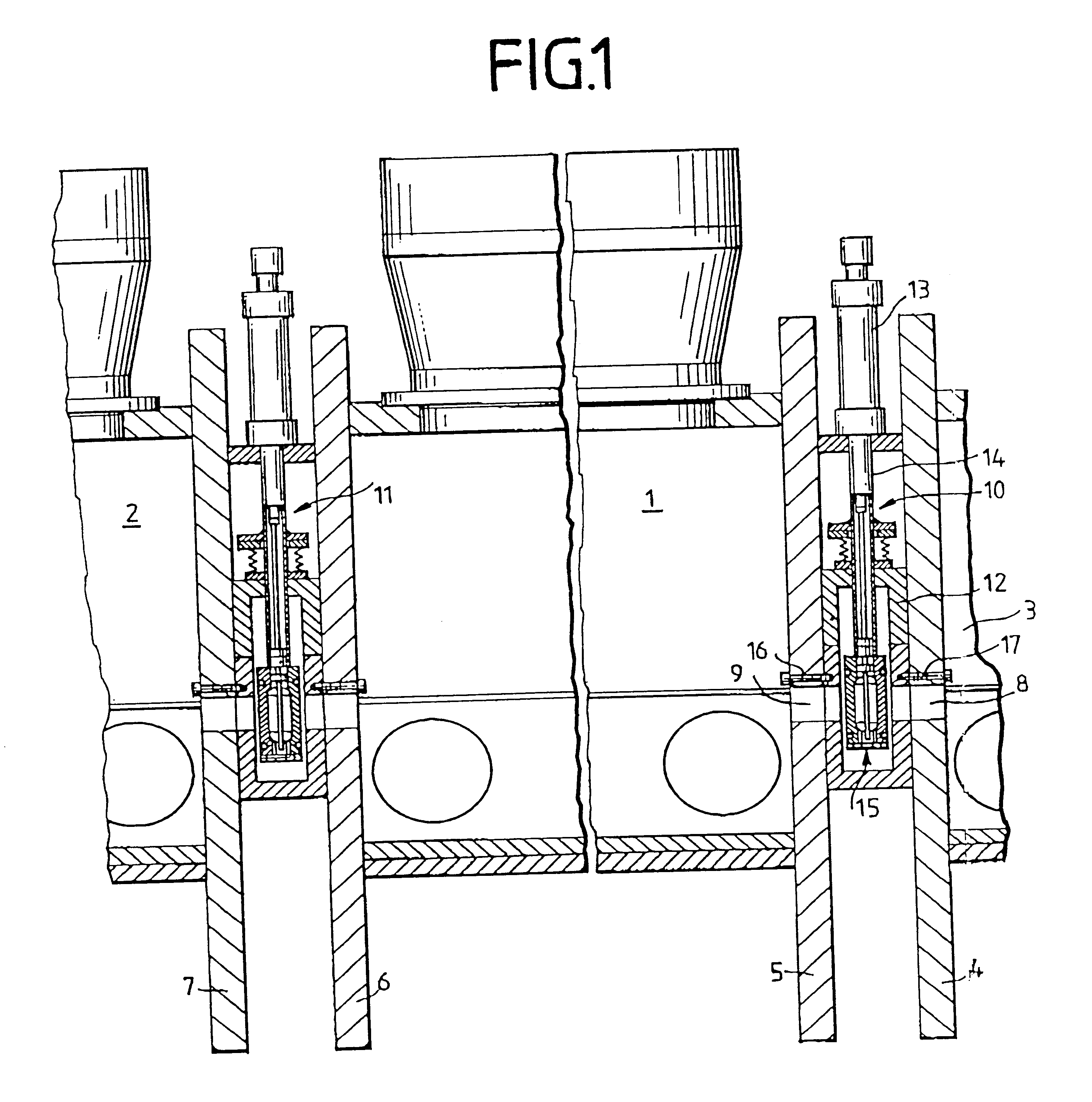
The lifting element is able to press unifo...


PUM

PropertyMeasurementUnit
Pressureaaaaaaaaaa
Lengthaaaaaaaaaa
Vacuumaaaaaaaaaa

Abstract

A gate valve (1) is constructed for the simultaneous blocking or clearing of two rectangular passage openings (8,9) of two chamber walls (4,5) that are provided between two vacuum chambers (1,3) and aligned with one another. To this end, it has two valve plates (20, 21), which are a component of a slider (15), which is situated so that it can move with play from a position clearing the passage openings (8,9) to a position which closes the passage openings (8,9). To move the valve plates (20,21) to the closing setting against the passage openings (8,9) on the slider (15), at least one lifting element (24), which is acted on by pressure, is provided.

Description

INTRODUCTION AND BACKGROUNDThe present invention concerns a gate valve to simultaneously shut off or clear two rectangular passage openings that are provided between two vacuum chambers which are aligned with one another and which have a low height and a large width on the order of magnitude of up to several meters, wherein the gate valve has two valve plates opposite one another to close the passage openings.Gate valves of the preceding type are needed, for example, in sputtering units in which glass passes several vacuum chambers placed one behind the other to be coated with an antireflection layer, for example, by sputtering. In such production units several vacuum chambers are constructed mostly as sputtering chambers. A one-gate chamber and many times also a buffer chamber are connected upstream from it, such that it is necessary for the glass to be able to move into the pertinent chamber via passage openings that can be closed.Up to now the passage openings have been closed by...

Claims


Application Information

Patent Timeline
IPC IPC(8): C23C14/56
CPCC23C14/568
Inventor SAUER, ANDREASSCHUHMACHER, MANFREDKUNZ, JOHANNESJOOS, GERHARD
Owner APPLIED MATERIALS GMBH & CO KG
Why Eureka
Try Eureka