Grounding of a shaft

a shaft and grounding technology, applied in the field of transmission, can solve the problems of increasing the problem of microampere current, increasing the problem, and damage to the bearing, so as to reduce the friction between the third component and the surface, improve the wear behavior, and increase the transfer resistance between the first and third components.

Inactive Publication Date: 2017-12-28
ZF FRIEDRICHSHAFEN AG +1
View PDF0 Cites 1 Cited by
  • Summary
  • Abstract
  • Description
  • Claims
  • Application Information

AI Technical Summary

Benefits of technology

[0021]In an also preferred further development, the contact consists at least in part of hardened steel. Hardened steel can be produced by transformation hardening, precipitation hardening or cold-work hardening. The use of hardened steel is first enabled by the bracing of the contact against a radially extending surface. Compared with the solutions known from the prior art, this makes for improved wear behavior.
[0022]Relative to the first component, the third component can be positioned concentrically or eccentrically. In a concentric arrangement a central axis of the third component, preferably an axis of symmetry relative to which the third component is rotationally symmetrical, coincides with the rotational axis of the first component. In this case the face of the first component against which the third component is braced is preferably of circular shape. In particular, the surface can be punctiform. A concentric arrangement of the third component has the advantage that the wear that occurs due to friction between the third component and the surface is minimized.
[0023]In an eccentric arrangement of the third component, a central axis of the third component, preferably the symmetry axis relative to which the third component is rotationally symmetrical, extends a distance away from the rotational axis of the first component, the distance being different from zero. In this case the face of the first component against which the third component is braced is preferably shaped as a circular ring. The eccentric arrangement of the third component avoids the possibility that as a result of corrosion, the transfer resistance between the first and third components will increase.

Problems solved by technology

The result is damage to the bearing, which can ultimately lead to failure.
However, more recent research has yielded the knowledge that even very small currents, i.e. currents in the microampere range, can cause damage to bearings.
The means described earlier are not suitable for avoiding currents in the microampere range when used in an oily environment.
This problem becomes more acute, the faster the bearing to be grounded is rotating.

Method used


Image

  • Grounding of a shaft
  • Grounding of a shaft

Examples


Embodiment Construction

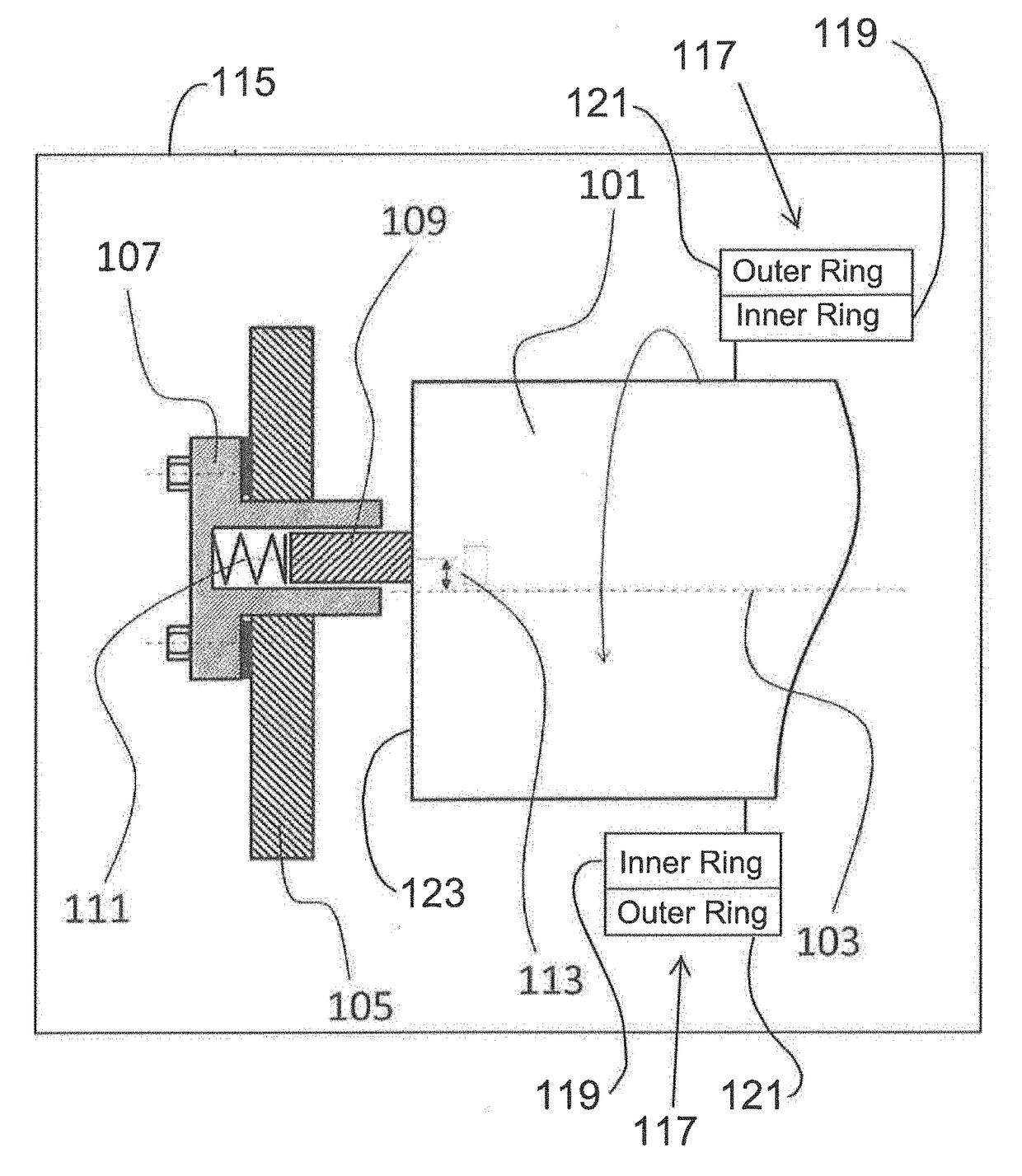
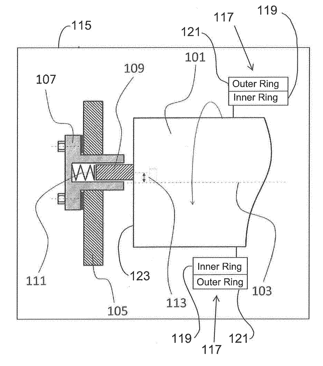
[0025]The shaft 101 of a transmission 115 has two end-faces with only one end-face 123 being shown in the FIGURE. The shaft 101 is mounted so that it can rotate about a rotational axis 103. The shaft 101 shown in the FIGURE is electrically connected to at least part of a bearing 117, such as a roller bearing. In particular, by virtue of the bearing 117, the shaft 101 can rotate—for example in the housing 105. This entails fixing the shaft 101 in an inner ring 119 and an outer ring 121 of the bearing 117. Also shown in the FIGURE is a transmission housing 105. To the transmission housing 105 are attached means 107 for grounding the shaft 101. The means 107 are electrically connected to the transmission housing 105. Furthermore, the means 107 comprise an electrically conductive pin 109. This is loaded by a spring 111 and pressed against the shaft 101, so that an electrically conductive connection is formed between the shaft 101 and the transmission housing 105.

[0026]The means 107 with...


PUM


Abstract

A transmission having a first component (101) mounted so as to rotate, a rotationally fixed second component (105) and a third component (107). The first component has a radially extending face and the third component (107) is fixed in the second component (105). The third component (107) is braced against the face and the third component (107) electrically connects the face and the second component (105) to one another.

Description

[0001]This application claims priority from German patent application serial no. 10 2016 211 616.9 filed Jun. 28, 2016.FIELD OF THE INVENTION[0002]The invention concerns a transmission.BACKGROUND OF THE INVENTION[0003]Electric currents can give rise to decarburiza ion and sparking in bearings. The result is damage to the bearing, which can ultimately lead to failure.[0004]To avoid the flow of current in a bearing, various solutions are known from the prior art which are designed to achieve potential equalization. These include carbon brushes, shaft grounding rings and telescopic brushes. Such means are suitable for avoiding currents in the range of a few milliamperes to several amperes.[0005]However, more recent research has yielded the knowledge that even very small currents, i.e. currents in the microampere range, can cause damage to bearings. Such currents seem to be responsible for the production of so-termed White Etching Cracks (WEC).[0006]The means described earlier are not s...

Claims


Application Information

Patent Timeline
Patent Type & Authority Applications(United States)
IPC IPC(8): B60R16/06H05F3/04
CPCH05F3/04B60R16/06F16H57/00H02K11/40
Inventor TENCKHOFF, GEORGENGELEN, KURTMARTIN BARRIOS, ALEJANDRO
Owner ZF FRIEDRICHSHAFEN AG
Why Eureka
Try Eureka