Method of modifying the coupling geometry in shroud band segments of turbine moving blades

a technology of shroud band segments and turbines, which is applied in the direction of machines/engines, manufacturing tools, other domestic articles, etc., can solve the problems of reducing the efficiency of the plant and undesirably high wear on the existing turbine stag

Inactive Publication Date: 2005-05-12
ALSTOM TECH LTD
View PDF11 Cites 1 Cited by
  • Summary
  • Abstract
  • Description
  • Claims
  • Application Information

AI Technical Summary

Benefits of technology

[0013] A further method according to the present invention for modifying an existing casting mold for a turbine moving blade having a shroud band segment, for a changed geometry of the coupling angle, has the following steps: calculation of a modified coupling geometry; removal of casting mold material situated inside the modified coupling geometry; and/or application of additional casting mold material, which is not present, outside the modified coupling geometry; reworking the removal and/or application zones. This modification e

Problems solved by technology

On account of the abovementioned factors which affect the shroud band coupling, even small changes to the turbine design of individual turbine stages, for example by conversion of a turbine stage or through chang

Method used


Image

  • Method of modifying the coupling geometry in shroud band segments of turbine moving blades
  • Method of modifying the coupling geometry in shroud band segments of turbine moving blades
  • Method of modifying the coupling geometry in shroud band segments of turbine moving blades

Examples


Embodiment Construction

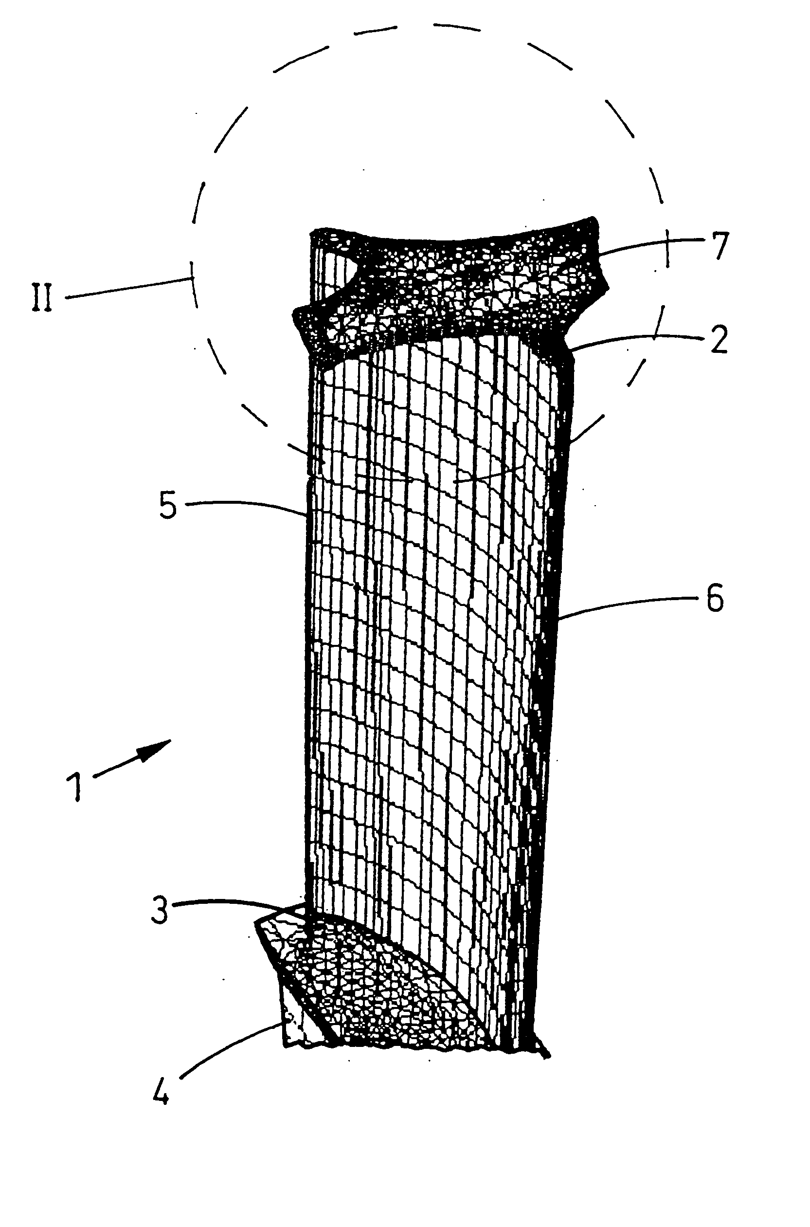
[0022]FIG. 1 shows a perspective view of a lattice model of a turbine moving blade 1 having a shroud band segment 7. The turbine moving blade 1 has a blade tip 2 at its top end and a blade root 3 at its bottom end, the blade root 3 continuing in a shank 4 (shown only approximately). The airfoil leading edge 5 is shown on the left-hand side of the drawing and the airfoil trailing edge 6 is shown on the right-hand side of the drawing.

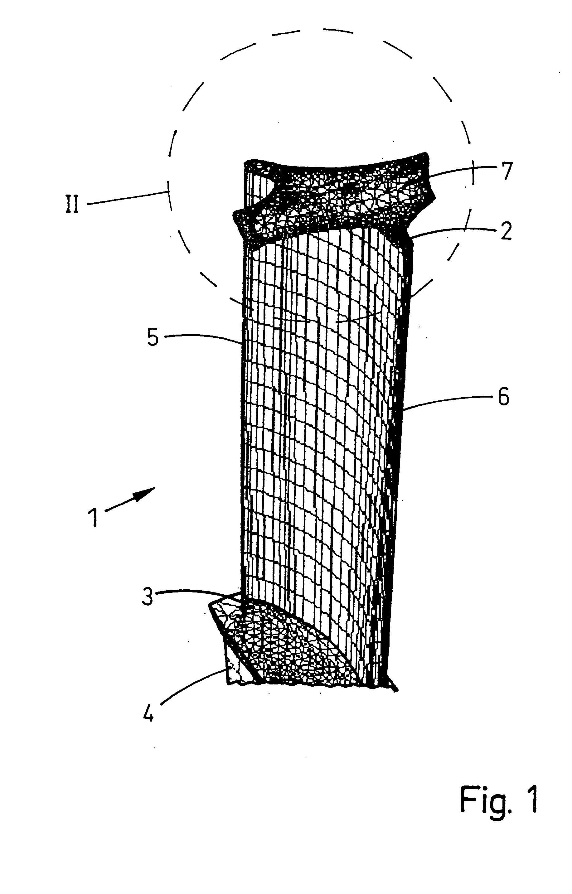
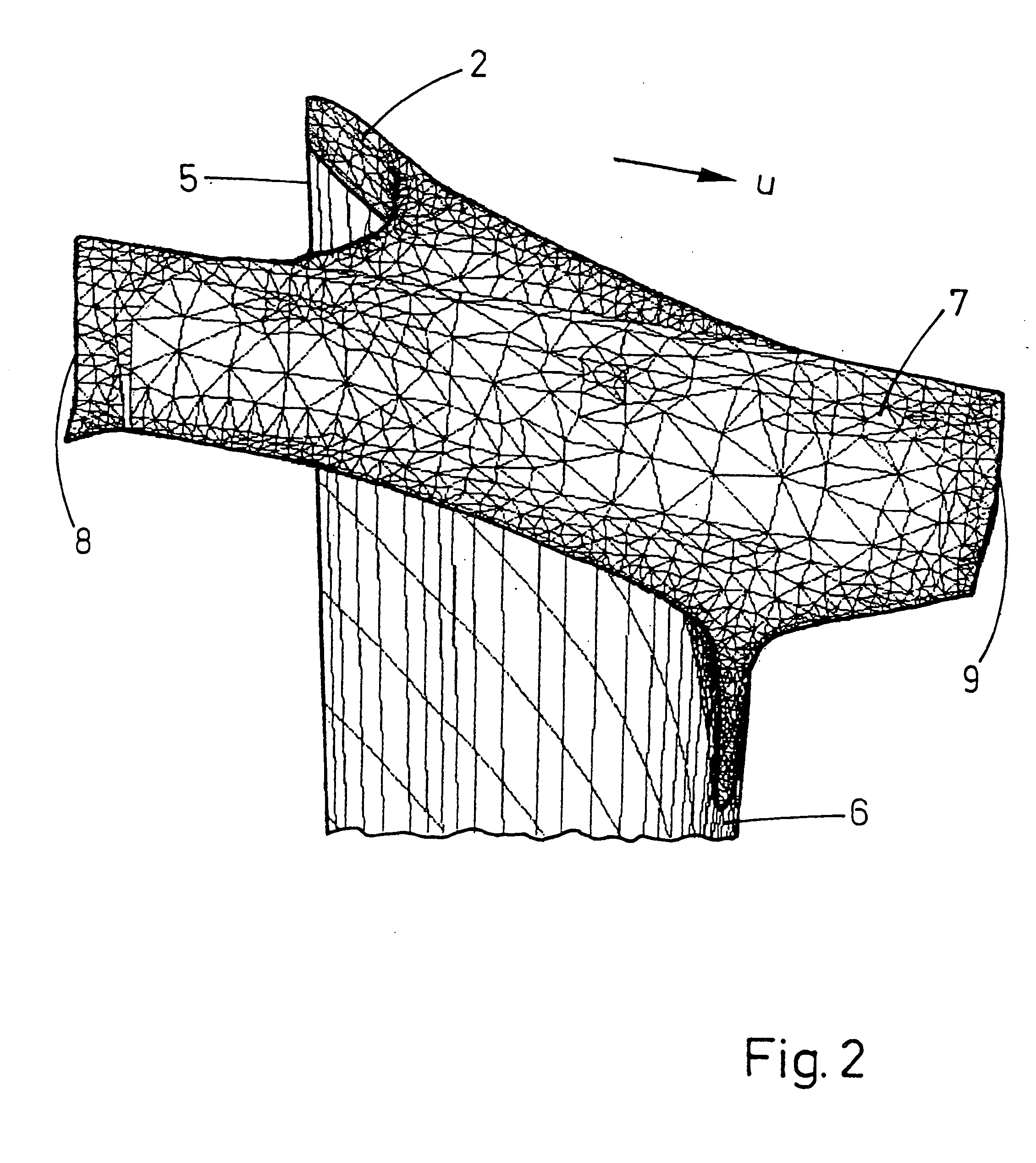
[0023] As can be seen in particular in FIG. 2 of the illustration of the detail II from FIG. 1, the shroud band segment 7 on the blade tip 2 runs essentially transversely to the airfoil chord running between the airfoil leading edge 5 and the airfoil trailing edge 6 and parallel to the circumferential direction U. In this case, the shroud band segment 7 does not extend over the entire blade depth but only to a region in the blade center. The transition between the shroud band segment 7 and the blade tip 2 is determined by transition radii. Furthermore, c...


PUM

PropertyMeasurementUnit
Angleaaaaaaaaaa
Angleaaaaaaaaaa
Angleaaaaaaaaaa

Abstract

A method of modifying a coupling geometry in a shroud band segment of a turbine moving blade includes the following steps: calculation of a modified coupling geometry; removal of shroud band material situated outside the modified coupling geometry; and/or application of additional material not present inside the modified coupling geometry; reworking the removal and/or application zones. The method avoids disadvantages of the prior art and provides improved wear behavior in the coupling region so as to prolong the life of the turbine blades in an effective and inexpensive manner.

Description

[0001] Priority is claimed to German Patent Application No. 103 28 310.2, filed on Jun. 23, 2003, the entire disclosure of which is incorporated by reference herein. [0002] The present invention relates to a method of modifying a coupling geometry in a shroud band segment of a turbine moving blade. BACKGROUND [0003] In turbine stages, it is known to provide turbine moving blades with a shroud band. In this case, the shroud band coupling of the blades or blade segments lying next to one another is characterized by a defined coupling angle, which, however, is affected by centrifugal forces acting on the blades, by the blade untwisting, by the shroud band stretching, by the temperature of the working medium, etc. The stresses which act during the mutual support of the blades during operation can in turn be controlled by the coupling angle and the coupling area. Such turbine moving blades having a shroud band segment are described, for example, in German patent DE 36 20 162 C2, related ...

Claims


Application Information

Patent Timeline
IPC IPC(8): F01D5/00F01D5/22
CPCF01D5/005F01D5/225Y10T29/49336Y10T29/49716Y10T29/49318Y10T29/49316
Inventor HAEHNLE, HARTMUTNAGLER, CHRISTOPHSCHWARZ, INGO
Owner ALSTOM TECH LTD
Why Eureka
Try Eureka