Doctor blade

a blade and blade technology, applied in the field of blades, can solve the problems of uncontrollable release of printing ink on the printing carrier, unevenness or irregularities, corresponding wear, etc., and achieve the effect of improving wear resistance and precise scraping

Active Publication Date: 2015-09-15
DAETWYLER SWISSTEC
View PDF35 Cites 1 Cited by
  • Summary
  • Abstract
  • Description
  • Claims
  • Application Information

AI Technical Summary

Benefits of technology

[0011]It is therefore an object of the invention to provide a doctor blade of the type used in the technical field mentioned at the outset which has improved wear resistance and allows precise scraping-off, in particular of printing ink, during the entire life.
[0012]The object is achieved by providing a doctor blade, in particular for scraping printing ink from a surface of a printing plate, which comprises a flat and longitudinal base element having a working edge region formed in a longitudinal direction, where the working edge region is coated with at least a first coating based on a nickel-phosphorus alloy, wherein the first coating contains at least one additive component for improving the wear behavior of the doctor blade, where the at least one additive component comprises hard material particles, wherein the hard material particles comprise both SiC and diamond, with the particle size of the SiC being greater than the particle size of the diamond. According to the invention, the first coating contains at least one additive component for improving the wear behavior of the doctor blade.
[0013]For the purposes of the present invention, an additive component for improving the wear behavior of the doctor blade is, in particular, particles dispersed in the first coating and / or chemical substances which have been mixed in.

Problems solved by technology

Unevennesses or irregularities in the working edges of the doctor blade which are in contact with the printing cylinder lead, for example, to incomplete scraping of the printing ink from the ridges of the printing cylinders.
This can result in uncontrolled release of printing ink on the printing carrier.
The working edges are therefore, particularly in the case of rotary printing presses, subjected to high mechanical stresses which result in corresponding wear.
However, doctor blades which have been coated in this way are still not fully satisfactory in respect of the life and wear resistance.
In addition, it has been found that when such doctor blades are used, uncontrolled streaking can occur, especially in the running-in phase, which is likewise undesirable.

Method used


Image

  • Doctor blade
  • Doctor blade
  • Doctor blade

Examples


Embodiment Construction

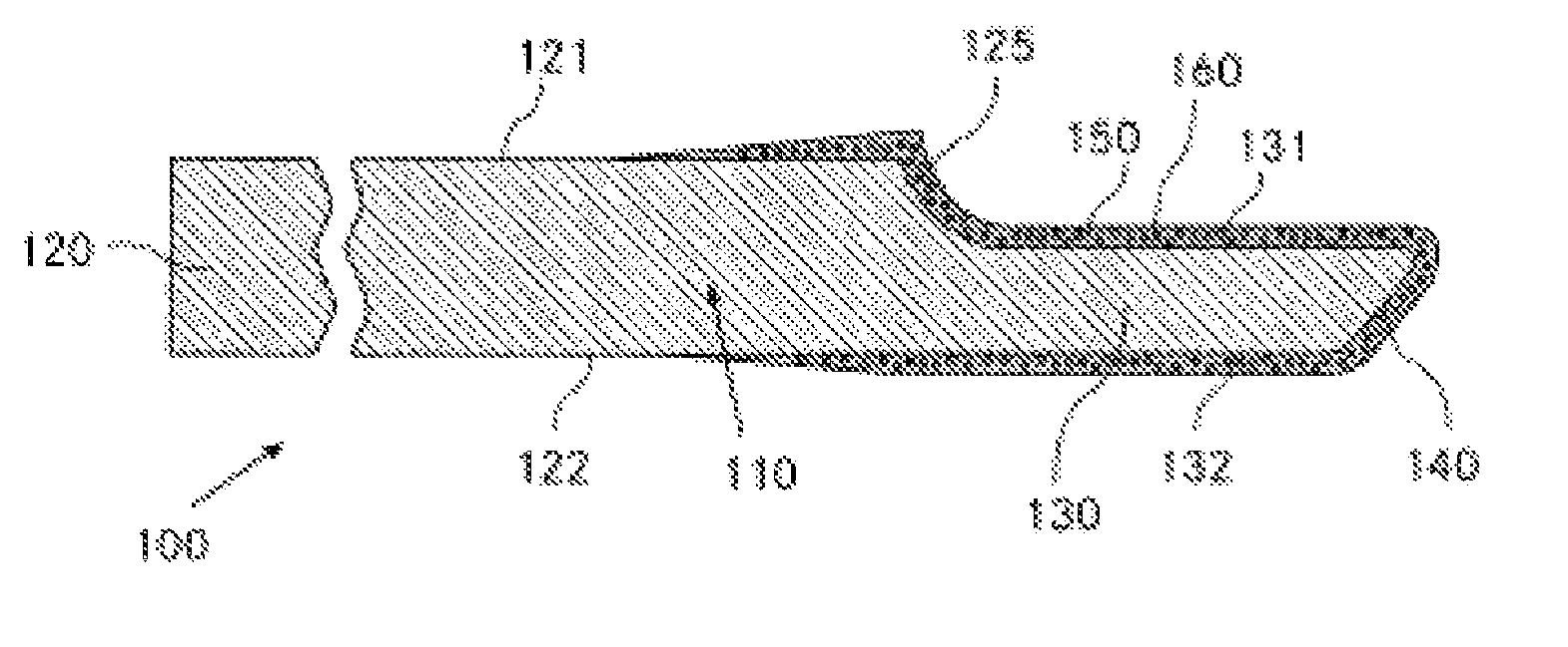
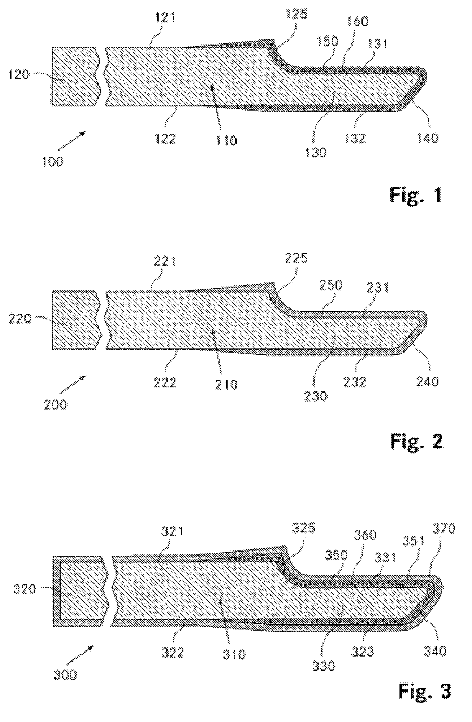
[0125]FIG. 1 depicts a lamellar doctor blade 100 according to the invention in cross section. The lamellar doctor blade 100 comprises a base element 110 made of steel which on the left-hand side in FIG. 1 has a rear region 120 having an essentially rectangular cross section. The rear region 120 is provided as a fastening region in order to hold the lamellar doctor blade in, for example, an appropriate holding device of a printing machine. The doctor blade thickness measured from the upper side 121 to the under side 122 of the rear region is about 0.2 mm. The length of the base element 110 or the lamellar doctor blade 100 measured perpendicular to the plane of the plate is, for example, 1000 mm.

[0126]On the right-hand side in FIG. 1, the base element 110 is tapered stepwise from the upper side 121 of the rear region 120 to form a working edge 130. An upper side 131 of the working edge 130 lies on a plane below the plane of the upper side 121 of the rear region 120 but is essentially ...


PUM


Abstract

A doctor blade for scraping printing ink from a surface of a printing plate, comprising a flat and elongated main body having a working edge area formed in a longitudinal direction, the working edge area being coated with at least one first coating on the basis of a nickel-phosphorus alloy, and is characterized in that the first coating contains at least one additional component for improving the wear behavior of the doctor blade.

Description

CROSS-REFERENCE TO RELATED APPLICATIONS[0001]This application claims priority to PCT Application No. PCT / CH2010 / 000014 filed Jan. 20, 2010, which application is incorporated herein by reference and made a part hereof.BACKGROUND OF THE INVENTION[0002]1. Field of the Invention[0003]The invention relates to a doctor blade, in particular for scraping printing ink from a surface of a printing plate, which comprises a flat and elongated base element having a working edge region formed in a longitudinal direction, where the working edge region is coated with at least a first coating based on a nickel-phosphorus alloy. The invention further relates to a process for producing a doctor blade.[0004]2. Description of the Related Art[0005]Doctor blades are used in the printing industry, especially for scraping excess printing ink from the surfaces of printing cylinders or printing rollers. Particularly in the case of gravure printing and flexographic printing, the quality of the doctor blade has...

Claims


Application Information

Patent Timeline
Patent Type & Authority Patents(United States)
IPC IPC(8): B41F9/10B41N10/00B05C11/04B41F31/04
CPCB41N10/005B05C11/045B41F9/1072B41F31/04
Inventor BRUDERMANN, HANS JORGSTILTZ, SIBYLLEHUGLI, ANDREAS
Owner DAETWYLER SWISSTEC
Why Eureka
Try Eureka