Apparatus and method for using emitting diodes (LED) in a side-emitting device

Inactive Publication Date: 2005-04-21
EATON INTELLIGENT POWER LIMITED
View PDF85 Cites 54 Cited by
  • Summary
  • Abstract
  • Description
  • Claims
  • Application Information

AI Technical Summary

Benefits of technology

[0007] The invention provides very efficient collection efficiency of the energy radiating form an LED, and then distributes this energy into a planarized 360 degree light pattern with extraordinary control. The invention furth

Problems solved by technology

The light radiating from the lamp above and below 45 degrees does not bec

Method used


Image

  • Apparatus and method for using emitting diodes (LED) in a side-emitting device
  • Apparatus and method for using emitting diodes (LED) in a side-emitting device
  • Apparatus and method for using emitting diodes (LED) in a side-emitting device

Examples


Embodiment Construction

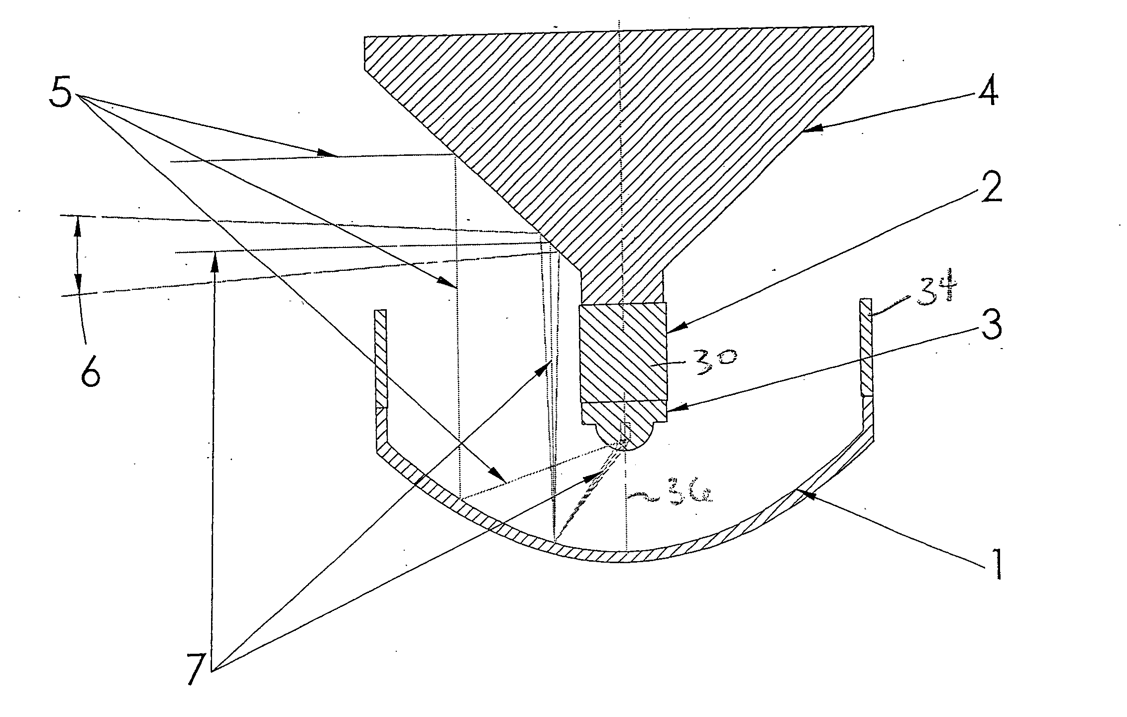
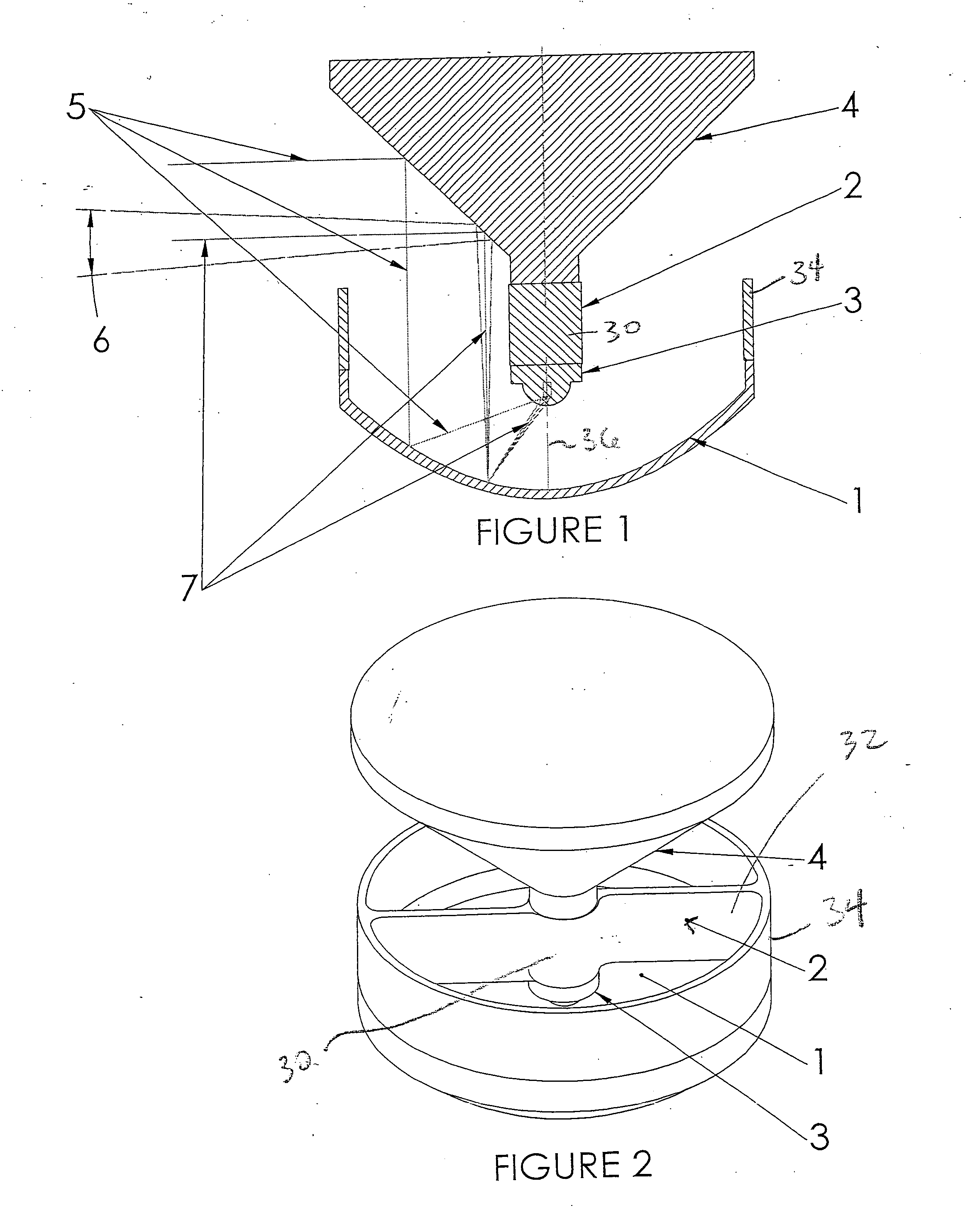
[0036] In FIGS. 1 and 2, an LED 3 is situated over or relative to a concave reflector 1 in such a manner to collect substantially all the energy radiated from LED 3 onto the concave reflective surface of reflector 1. LED 3 is a conventional LED integrated package, which includes a packaged chip in which the light emitting junction has been formed and typically providing with a hemispherical lens for directing the emitted light in a Lambertian pattern. However, it must be clearly understood that the invention can be used with any LED configuration or packaging now known or later devised. LED 3 is connected through wires or conductive leads (not shown) to a conventional drive circuit (not shown) powered in turn by a battery (not shown) or other conventional power source.

[0037] Heat sink2 provides positional alignment and thermal management for the LED 3. LED 3 is coupled to heat sink 2, which in the illustrated embodiment is best shown in FIG. 2 as including a cylindrical hub 30 to w...


PUM


Abstract

An LED having a predetermined direction of radiation is combined with a first and second reflector. The first reflector opposes the LED and has a predetermined direction of reflection. The direction of reflection of the first reflector opposes the direction of radiation of the LED. The second reflector has a predetermined azimuthal direction of reflection. The second reflector positioned relative to the first reflector to receive light from the first reflector and redirect the light into the azimuthal direction of reflection. The LED, first and second reflectors collectively comprise an illumination unit. A plurality of illumination units are axially stacked. In one embodiment of the stack, at least one illumination unit comprises an LED and second reflector of one illumination unit and a first reflector of an adjacent illumination unit in the stack of illumination units.

Description

RELATED APPLICATIONS [0001] The present application is related to U.S. Provisional Patent Application Ser. No. 60 / 494,469, filed on Aug. 12, 2003, which is incorporated herein by reference and to which priority is claimed pursuant to 35 USC 119.BACKGROUND OF THE INVENTION [0002] 1. Field of the Invention [0003] The invention relates to the field of light emitting diodes (LED) used in a side-emitting device. [0004] 2. Description of the Prior Art [0005] The invention collects substantially all the light or energy radiating from an LED source and redirects it into a 360 degree circular beam of light. The propagating beam is similar in its conical planar radiation pattern to that of the beam of a conventional lighthouse Fresnel lamp system. There are, however, several substantial differences between the invention and such prior art systems. In the prior art only a portion of the energy from the lamp is collected. With a traditional navigational lamp system, a lamp is placed at the axis...

Claims


Application Information

Patent Timeline
IPC IPC(8): F21S8/00F21V1/00F21V7/00F21V29/00
CPCF21V7/0008F21Y2101/02F21V29/004F21V7/0025F21V29/70F21Y2115/10
Inventor RHOADS, GREGHOLDER, RONALD GARRISON
Owner EATON INTELLIGENT POWER LIMITED
Why Eureka
Try Eureka