Formation evaluation through azimuthal measurements

a technology of azimuthal measurement and formation image, applied in the field of well logging, can solve the problem of not being able to provide formation images from neutron measurements

Active Publication Date: 2005-09-13
SCHLUMBERGER TECH CORP
View PDF21 Cites 45 Cited by
  • Summary
  • Abstract
  • Description
  • Claims
  • Application Information

AI Technical Summary

Benefits of technology

[0011]Another aspect of the invention relates to logging tools having azimuthal sensitivities. A neutron logging tool includes a housing adapted to move in a borehole; circuitry having memories for storing measurements of neutron-induced signals; a neutron source disposed in the housing; and at least one bank of detectors disposed in the housing spaced apart from the neutron source along an axis of the logging tool, wherein each of the at least one bank of detectors comprises a plurality of detectors disposed around a periphery of the housing such that the plurality of detectors are more sensitive to signals from an azimuthal direction, and wherein count rates detected by each of the plurality of detectors are separately stored in the memories.

Problems solved by technology

However, these methods cannot provide formation images from the neutron measurements.

Method used


Image

  • Formation evaluation through azimuthal measurements
  • Formation evaluation through azimuthal measurements
  • Formation evaluation through azimuthal measurements

Examples


Embodiment Construction

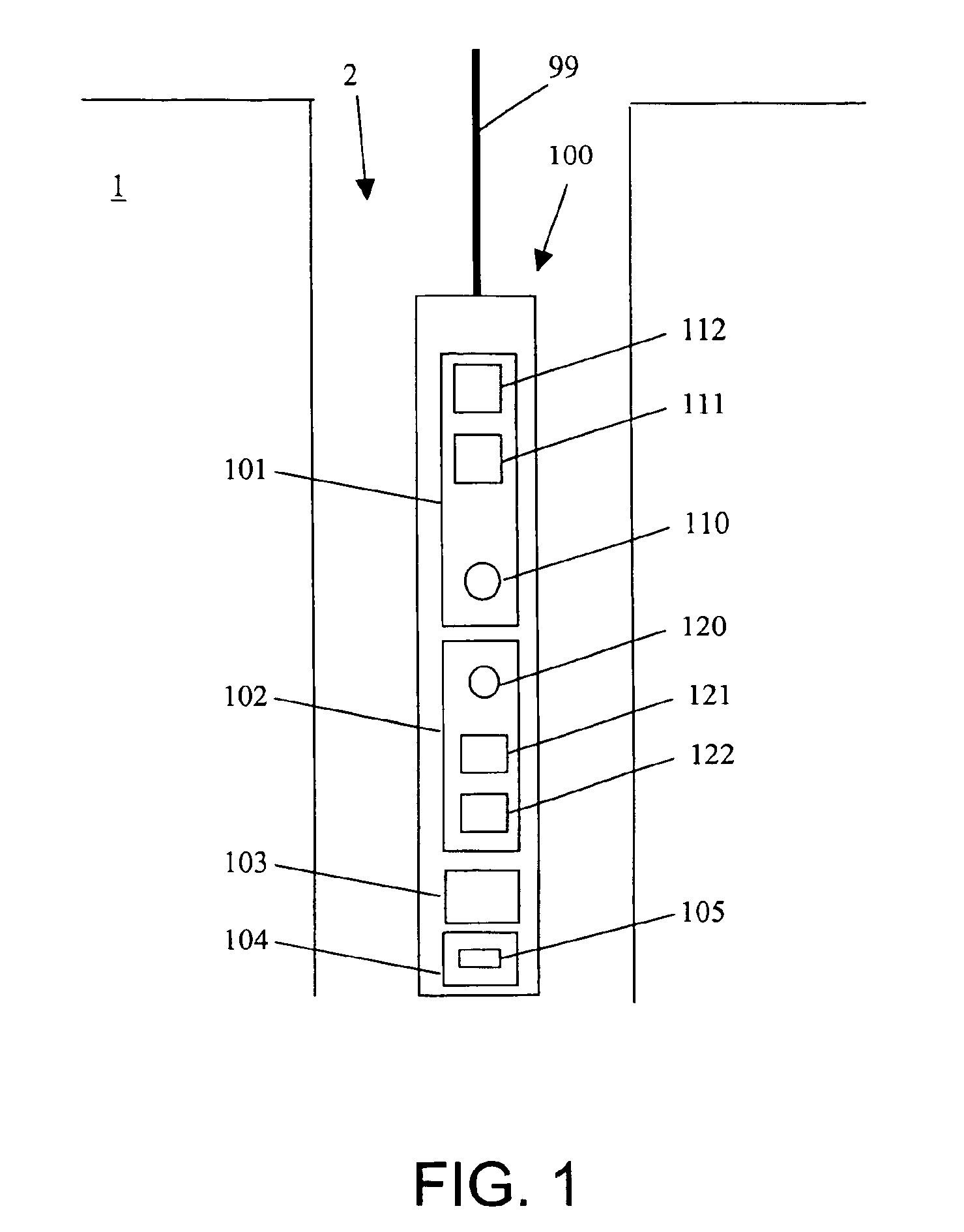
[0019]Embodiments of the invention relate to methods and apparatuses for logging and imaging earth formations using neutron tools. The logging techniques are based on improved neutron tools with the ability to detect neutron data having azimuthal information. Specifically, embodiments of the invention relate to methods for azimuthal measurements of neutron-induced signals and methods for analyzing these measurements. Methods of the invention make it possible to improve the accuracy of these measurements, to provide image-based analysis of neutron-induced signals, and to provide additional information previously unavailable to neutron logging. Embodiments of the invention may be applied to measurements in wireline, MWD / LWD, or logging-while-tripping (LWT) environments. In addition, embodiments of the invention may be combined with other measurements for analysis.

[0020]Azimuthal acquisition of neutron-induced signals may be achieved in several ways. In an LWD tool, for example, the az...


PUM


Abstract

A method for formation logging includes acquiring measurements of neutron-induced signals having azimuthal information using a neutron tool; processing the measurements into a plurality of azimuthal sector data for each acquisition interval; and deriving a selected parameter from the plurality of azimuthal sector data. A logging tool includes a housing adapted to move in a borehole; a circuitry having memories for storing neutron-induced measurements; a neutron source disposed in the housing; and at least one detector bank disposed in the housing spaced apart from the neutron source, wherein each of the at least one detector bank comprises at least one detector disposed around a periphery of the housing such that the at least one detector is more sensitive to signals from an azimuthal direction, and wherein count rates detected by each of the at least one detector are separately stored in the memories.

Description

BACKGROUND OF THE INVENTION[0001]1. Field of the Invention[0002]The present invention relates to the field of well logging. More specifically, the present invention relates to apparatus and methods for well logging using neutron tools.[0003]2. Background Art[0004]In traditional wireline (WL) well logging, a sonde is lowered into a borehole and data are collected as the tool is pulled uphole. The detectors in the sonde therefore make measurements as a function of depth or acquisition time, and the precise location of the detectors with respect to the circumference of the borehole at each depth or acquisition time, i.e., the azimuthal position, is generally disregarded. Measurements are typically recorded as a function of acquisition time (temporal intervals) and are later converted to measurements as a function of depth of the well (axial depth; spatial intervals). In this description, “acquisition intervals” are generally used to refer to either spatial or temporal intervals, i.e., ...

Claims


Application Information

Patent Timeline
Patent Type & Authority Patents(United States)
IPC IPC(8): E21B47/026E21B47/02G01V5/10G01V5/12
CPCE21B47/026G01V5/104G01V5/125
Inventor RADTKE, RICHARD J.EVANS, MICHAEL L.ADOLPH, ROBERT A.VILDE, LOICWIJEYESEKERA, NIHAL IAN
Owner SCHLUMBERGER TECH CORP
Why Eureka
Try Eureka