Method and device for normal correction of scanning data in imaging equipment

An imaging device and a technology for scanning data, applied in the field of medical imaging, which can solve problems such as image artifacts and reduce correction data acquisition time.

Active Publication Date: 2013-09-25
SHENYANG INTELLIGENT NEUCLEAR MEDICAL TECH CO LTD
View PDF2 Cites 23 Cited by
  • Summary
  • Abstract
  • Description
  • Claims
  • Application Information

AI Technical Summary

Problems solved by technology

[0007] In order to solve the above technical problems, embodiments of the present invention provide a method and device for normalizing and correcting scan dat...

Method used


Image

  • Method and device for normal correction of scanning data in imaging equipment
  • Method and device for normal correction of scanning data in imaging equipment
  • Method and device for normal correction of scanning data in imaging equipment

Examples


Embodiment 1

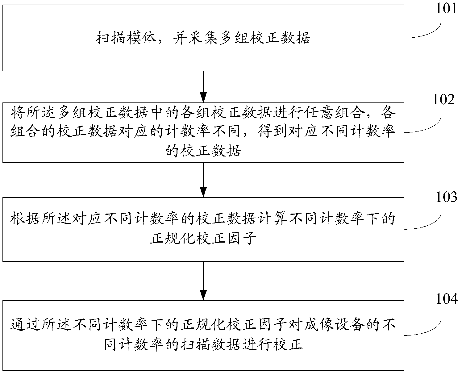
[0096] see figure 1 , which is a flowchart of a method for normalizing and correcting scan data in an imaging device disclosed in Embodiment 1 of the present invention, including the following steps:

[0097]Step 101: scanning the phantom, and collecting multiple sets of calibration data;

[0098] Use PET or PET / CT and other medical imaging equipment with PET to scan the phantom, and the activity of the scanned phantom can be determined according to the number of groups of collected calibration data. The higher the activity of the phantom, the fewer the number of groups collected, and the lower the activity of the scanned phantom. In addition, the activity of the phantom is also related to the type of scanning. Generally, the activity of the scanned phantom is lower when 3D scanning is used than when 2D scanning is used.

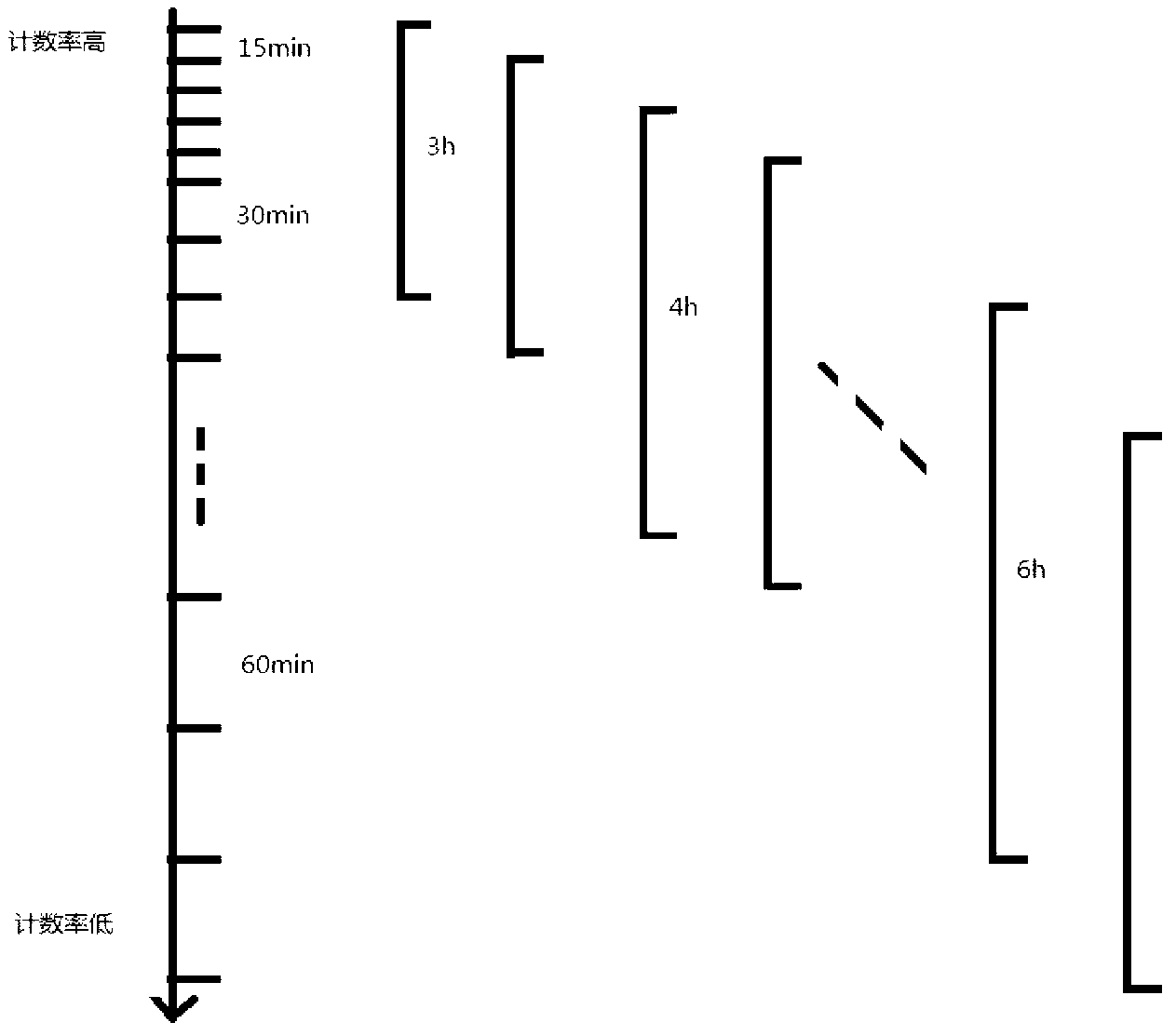
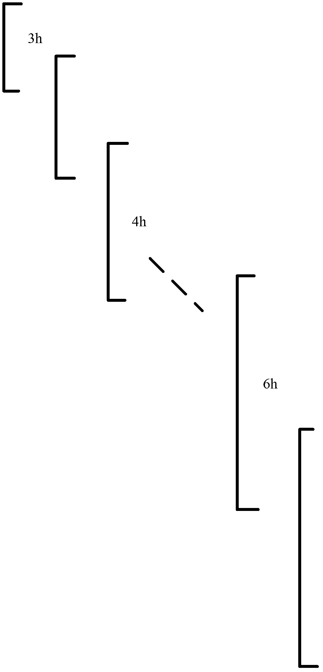
[0099] In the technical solution of the present invention, preferably, in order to obtain more calibration data corresponding to different count rates, ma...

Embodiment 2

[0115] When the technical solution of the present invention uses the CBN method to calculate the normalized correction factors at different count rates, the scanned phantom in Embodiment 1 is a cylindrical phantom, and the collected correction data is the correction data of the cylindrical phantom, corresponding to different count rates. The calibration data is the calibration data of the cylindrical phantom corresponding to different count rates.

[0116] see Figure 5 , which is a flowchart of a method for normalizing and correcting scan data in an imaging device disclosed in Embodiment 2 of the present invention, including the following steps:

[0117] Step 501: scanning the cylindrical phantom, and collecting multiple sets of cylindrical phantom correction data;

[0118] In the CBN method, the formula for calculating the normalization correction factor is: NC uivj =ε ui ε vj b u b v c uimodD c vjmodD d uvrk f uv g uvr , where NC uivj is the normalization correc...

Embodiment 3

[0148] If the CBN method is used to calculate the normalized correction factor at different count rates, the normalized correction factor will also change with time due to the influence of the crystal efficiency factor that changes with time. Therefore, it is necessary to regularly update the normalized correction factor at different count rates. Normalize the correction factor so that the data are regularly corrected using the normalized correction factor at different count rates. The difference between this embodiment and the second embodiment is that it further includes a step of periodically updating the normalization correction factors under different count rates.

[0149] see Figure 7 , which is a flow chart of a method for normalizing and correcting scan data in an imaging device disclosed in Embodiment 3 of the present invention, the method specifically includes:

[0150] Wherein, the following steps 701-705 are applied to the link of calculating the normalization co...


PUM


Abstract

An embodiment of the invention discloses a method and a device for normal correction of scanning data in imaging equipment. The method includes scanning a model and acquiring a plurality of groups of correction data; optionally combining the groups of correction data to obtain correction data combinations corresponding to different counting rates, thus obtaining correction data corresponding to the different counting rates; calculating normal correction factors under the different counting rates according to the correction data corresponding to the different counting rates; and correcting scanning data different in counting rate in the imaging equipment through the normal correction factors under the different counting rates. The method and the device according to the embodiment have the advantages that acquisition time of correction data can be shortened and the problem of image artifacts caused by mismatch of the counting rates is also avoided.

Description

technical field [0001] The invention relates to the technical field of medical imaging, in particular to a method and a device for normalizing and correcting scanning data in imaging equipment. Background technique [0002] Nuclear medicine imaging equipment provides powerful tools for today's diagnostics. Both PET and CT are typical representatives of nuclear medicine imaging equipment, among which PET and SPECT are molecular functional imaging equipment, while CT and MR are anatomical imaging equipment. At present, two modal imaging devices are usually integrated clinically to form multi-modal imaging devices such as PET / CT, PET / MR and SPECT / CT. For example, the images provided by PET / CT multimodal imaging equipment not only have anatomical information, but also molecular function information, which provides a more accurate basis for medical clinical diagnosis. [0003] For medical imaging equipment with PET such as PET or PET / CT, it mainly detects the rays emitted from ...

Claims


Application Information

Patent Timeline
IPC IPC(8): A61B6/03
Inventor 朱传伟刘月李明
Owner SHENYANG INTELLIGENT NEUCLEAR MEDICAL TECH CO LTD
Why Eureka
Try Eureka