Apparatus and method for temperature correction and expanded count rate of inorganic scintillation detectors

a technology count rate, which is applied in the field of temperature correction and expanded count rate of inorganic scintillation detector, can solve the problems of difficult to compensate accurately over a given temperature range, strong temperature dependence and corresponding count rate limitations, and inability to meet the requirements of measurement, etc., and achieve the effect of expanding the count ra

Inactive Publication Date: 2006-07-25
LOS ALAMOS NATIONAL SECURITY
View PDF6 Cites 21 Cited by
  • Summary
  • Abstract
  • Description
  • Claims
  • Application Information

AI Technical Summary

Benefits of technology

[0016]In accordance with the purposes of the present invention, as embodied and broadly described herein, the present invention includes an apparatus and corresponding method for temperature correction and count rate expansion of inorganic scintillation detectors. A temperature sensor is attached to an inorganic scintillation detector. The inorganic scintillation detector, due to interaction with incident radiation, creates light pulse signals. A photoreceiver processes the light pulse signals to current signals. Temperature correction circuitry that uses a fast light component signal, a slow light component signal, and the temperature signal from the temperature sensor to corrected an inorganic scintillation detector signal output and expanded the count rate.

Problems solved by technology

Inorganic scintillation detectors, as traditionally understood, exhibit strong temperature dependence and corresponding count rate limitations.
The temperature dependence exhibited by inorganic scintillation detectors is nonlinear, and, thus, it is difficult to compensate accurately over a given temperature range. FIG. 2 shows the dependence of the scintillation light decay constant exhibited by Nal(Tl) due to the temperature of the Nal(Tl) crystal.
First, scintillators can be stabilized electronically by introducing an americium-241 seed and tracking the alpha peak and adjusting the gain of gamma peaks. However, the temperature response of alpha particles is different than for electrons generated by gamma-ray interactions, so additional temperature compensation is still required.
Second, mapping the temperature versus gain (FIG. 1) for the particular inorganic detector used and then offsetting the resultant output accordingly. In this method, a temperature sensor is attached to the scintillation material and the reading is used to adjust the gain. The problem of this approach is that the temperature versus gain curve is a function of both the pulse shaping time constant and the doping level of the inorganic scintillator. Doping is defined as the addition of a small amount of an impurity (e.g. thallium in a Nal crystal or cerium in a LaCl3 crystal) to boost the light output from the scintillation material (crystal).
Third, use a temperature dependent photomultiplier tube divider as taught in U.S. Pat. No. 6,407,390 issued on Jun. 18, 2002 by Csaba M. Rozsa. This method extends the scintillation detector operating range down to ambient temperatures above 0° C. by using linear segmented approximations with a fixed gain assigned to each linear segment. Note this method works only for ambient temperatures above 0° C.
However, this approach is applicable only if the LED light pulse follows the amplitude and shape changes of the light pulse produced by the scintillation detector due to changes in the ambient temperature.
Thus, this method does not work in the entire temperature range (−30° C. to +60° C.)

Method used


Image

  • Apparatus and method for temperature correction and expanded count rate of inorganic scintillation detectors
  • Apparatus and method for temperature correction and expanded count rate of inorganic scintillation detectors
  • Apparatus and method for temperature correction and expanded count rate of inorganic scintillation detectors

Examples


first embodiment

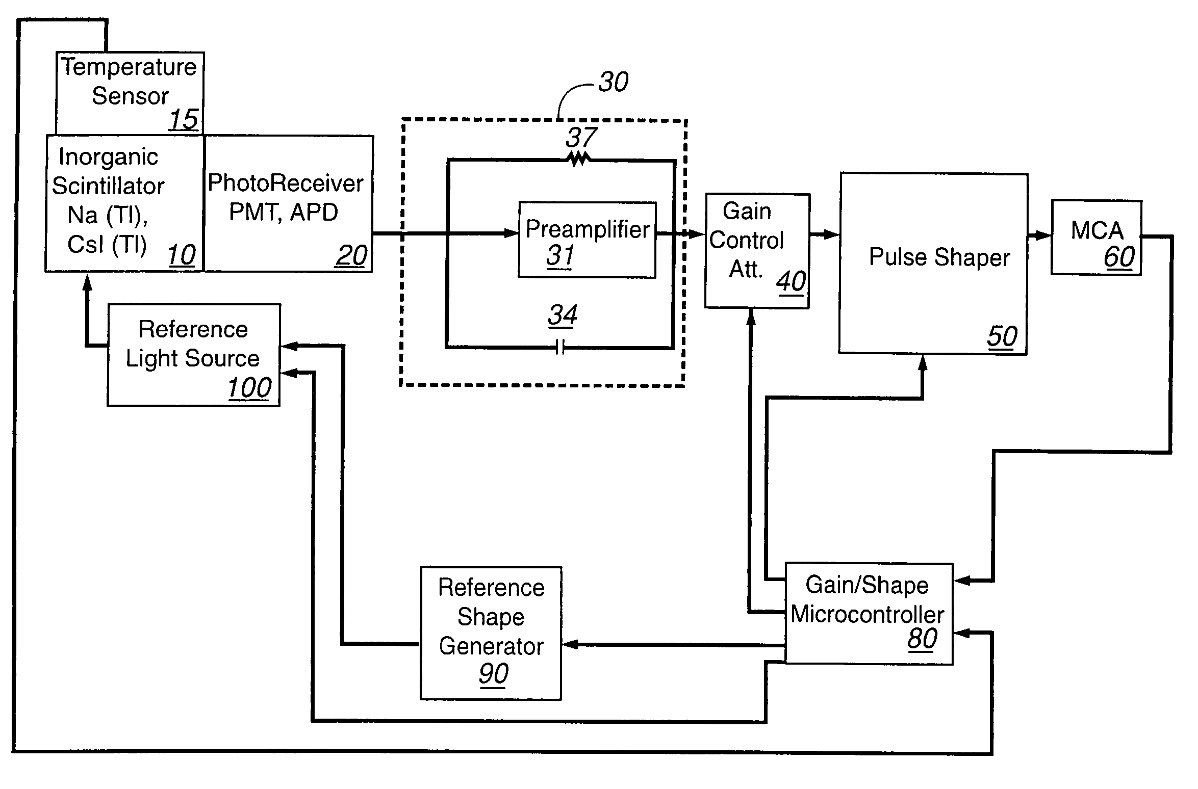
[0032]Referring now to FIG. 3, the present invention compensates for temperature using a standard preamplifier and pulse shaper setup. Inorganic scintillator 10 (e.g., Nal (Tl), Csl (Tl), LaCl3 (Ce), and the like) is optically coupled to photoreceiver 20 (e.g., photomultiplier tubes (PMTs), photodiodes, and avalanche photodiodes (APD)). Output from photoreceiver 20 is directed to temperature correction circuitry for temperature and gain correction that includes charge-sensitive preamplifier package 30, gain control attenuator 40, pulse shaper 50, and multi-channel analyzer (MCA) 60.

[0033]A feedback loop is used to adjust for ambient temperature changes affecting scintillator 10. The feedback loop incorporates microcontroller 80, reference shape generator 90, and reference light source 100.

[0034]Charge-sensitive preamplifier package 30 comprises high-impedance inverting amplifier 31 connected in parallel with capacitor 34 and resistor 37. Resistor 37 is used to prevent circuit satura...

second embodiment

[0070]Both modes of the second embodiment provide a stable reference light source that is injected into scintillator 10 by reference light source 100 and collected by photoreceiver 20. Thus, the stability of the light interface between scintillator 10 and photoreceiver 20 is included in the system feedback loop. Reference shape generator 90 provides a reference pulse to reference light source 100 that closely approximates scintillator 10 detected pulse shapes and corresponding temperature dependence. The amplitude of the reference pulse is selected so that the reference pulse is positioned at the upper end of the scale on MCA 60. Gain microcontroller 80 calculates the centroid of the reference pulse and corrects the gain via gain control attenuator 40 in order to maintain the reference pulse in the specified position. The frequency of the reference pulses is determined by the speed of temperature changes in scintillator 10 and stability of the feedback loop system.

[0071]The second e...


PUM


Abstract

The present invention includes an apparatus and corresponding method for temperature correction and count rate expansion of inorganic scintillation detectors. A temperature sensor is attached to an inorganic scintillation detector. The inorganic scintillation detector, due to interaction with incident radiation, creates light pulse signals. A photoreceiver processes the light pulse signals to current signals. Temperature correction circuitry that uses a fast light component signal, a slow light component signal, and the temperature signal from the temperature sensor to corrected an inorganic scintillation detector signal output and expanded the count rate.

Description

STATEMENT REGARDING FEDERAL RIGHTS[0001]This invention was made with government support under Contract No. W-7405-ENG-36 awarded by the U.S. Department of Energy. The government has certain rights in the invention.FIELD OF THE INVENTION[0002]The present invention relates generally to inorganic scintillation detectors, and, more particularly, to temperature correction and expanded count rate of inorganic scintillation detectors.BACKGROUND OF THE INVENTION[0003]Inorganic scintillation detectors convert incoming radiation (alpha, beta, or gamma) into pulses of light (optical photons). The amplitude (and frequency) of the pulses of light corresponds directly to the energy imparted by the incident radiation. Inorganic scintillation detectors (Nal(Tl), Csl(Tl), Csl(Na), BGO, LaCl3, and the like) have been used for many years in gamma ray spectrometry and have numerous commercial applications. Inorganic scintillation detectors, as traditionally understood, exhibit strong temperature depend...

Claims


Application Information

Patent Timeline
Patent Type & Authority Patents(United States)
IPC IPC(8): G01T1/208G01T1/20
CPCG01T1/20
Inventor IANAKIEV, KIRIL D.HSUE, SIN TAOBROWNE, MICHAEL C.AUDIA, JEFFREY M.
Owner LOS ALAMOS NATIONAL SECURITY
Why Eureka
Try Eureka