Assembly structure of a back light module

a back light module and assembly structure technology, applied in the field of back light modules, can solve the problems of increased manufacturing cost, high cost, inconvenient use, etc., and achieve the effect of increasing the manufacturing cost, not only high cost, but also large volum

Inactive Publication Date: 2005-04-21
CANDLE LAB
View PDF13 Cites 15 Cited by
  • Summary
  • Abstract
  • Description
  • Claims
  • Application Information

AI Technical Summary

Benefits of technology

[0007] It is therefore a primary objective of the claimed invention to provide an assembly structure of a back light module that can achieve effects of easy assembly and firm structure with the embedded structure of separated frames by interfered conjugation and contacting in multi points.
[0008] It is therefore another objective of the claimed invention to firmly fix the optical plate with the frame by the chute of the frame and the fixed support of the optical plat without using glue. The disadvantage of fixing by glue can be thoroughly solved.
[0009] It is therefore a further objective of the claimed invention to provide a back light module with advantages of low cost and easy assembly that differ to the traditional once-formed and glue-fixed frame.

Problems solved by technology

Since the intensity of the light is getting weaker with the distance, the light intensity at the central part of the diffusion plate is weaker than that at two sides, and the light intensity of the whole diffusion plate is not uniform.
The frame for this kind of assembly structure has not only high cost but also large volume that are inconvenient for packaging and transporting.
In addition, fixing by glue has problem in orientation and increases manufacture cost.
Furthermore, the traditional side projecting lamp need a metal device to fix the lamp and the direct type lamp also need a fixing device to fix the lamp that has the disadvantage of complex manufacture and uneasy assembly.

Method used


Image

  • Assembly structure of a back light module
  • Assembly structure of a back light module
  • Assembly structure of a back light module

Examples


Embodiment Construction

[0017] The present invention provides an assembly structure of a back light module that is equipped a multi-point structure intervened each other at the ends of the separated frame. With the chute at the sides of the frame, the optical plate can be assembled with the frames to acieve a firmly fixed back light module.

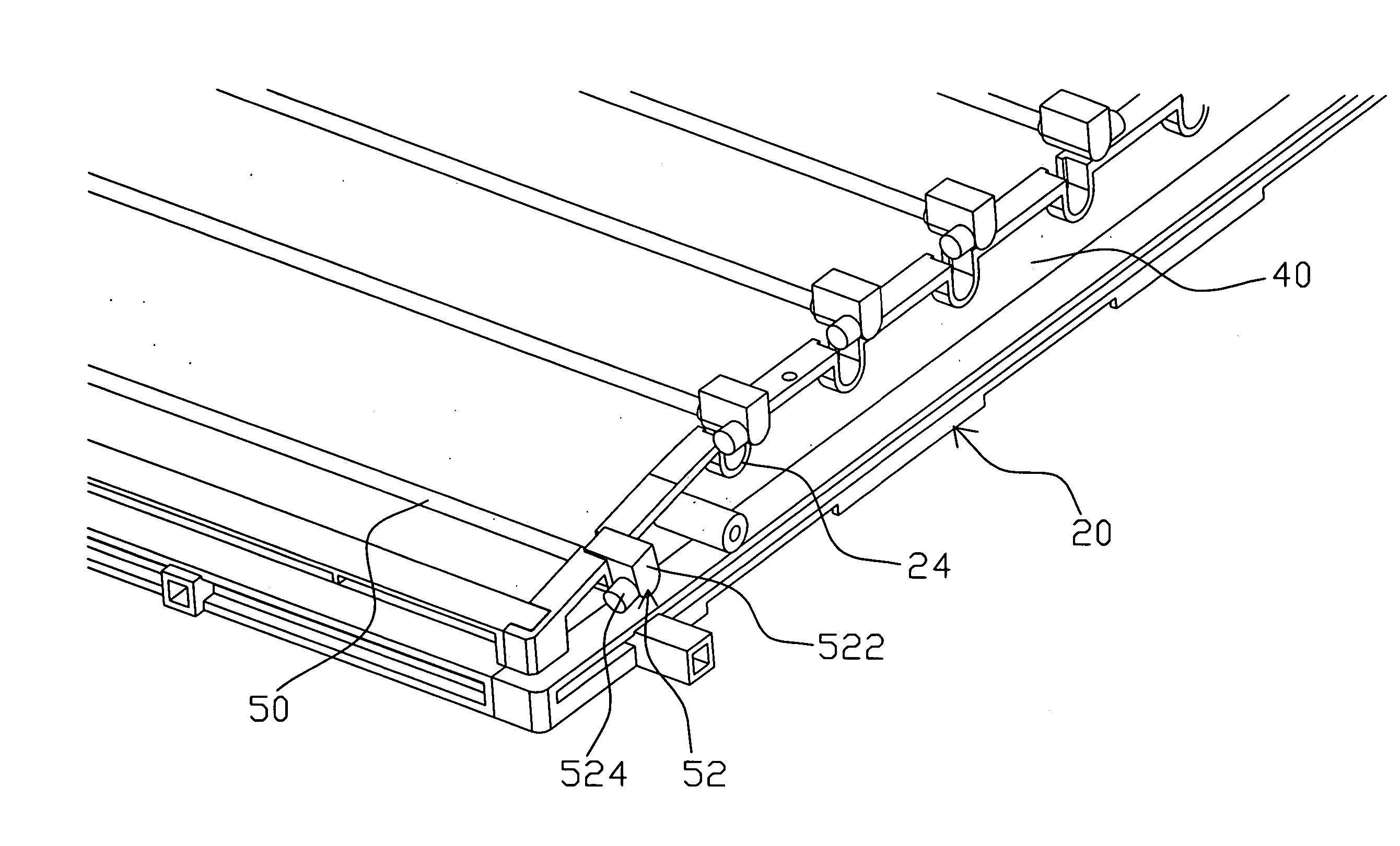
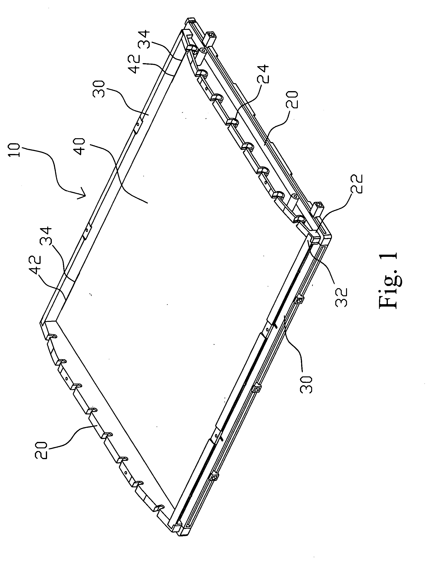
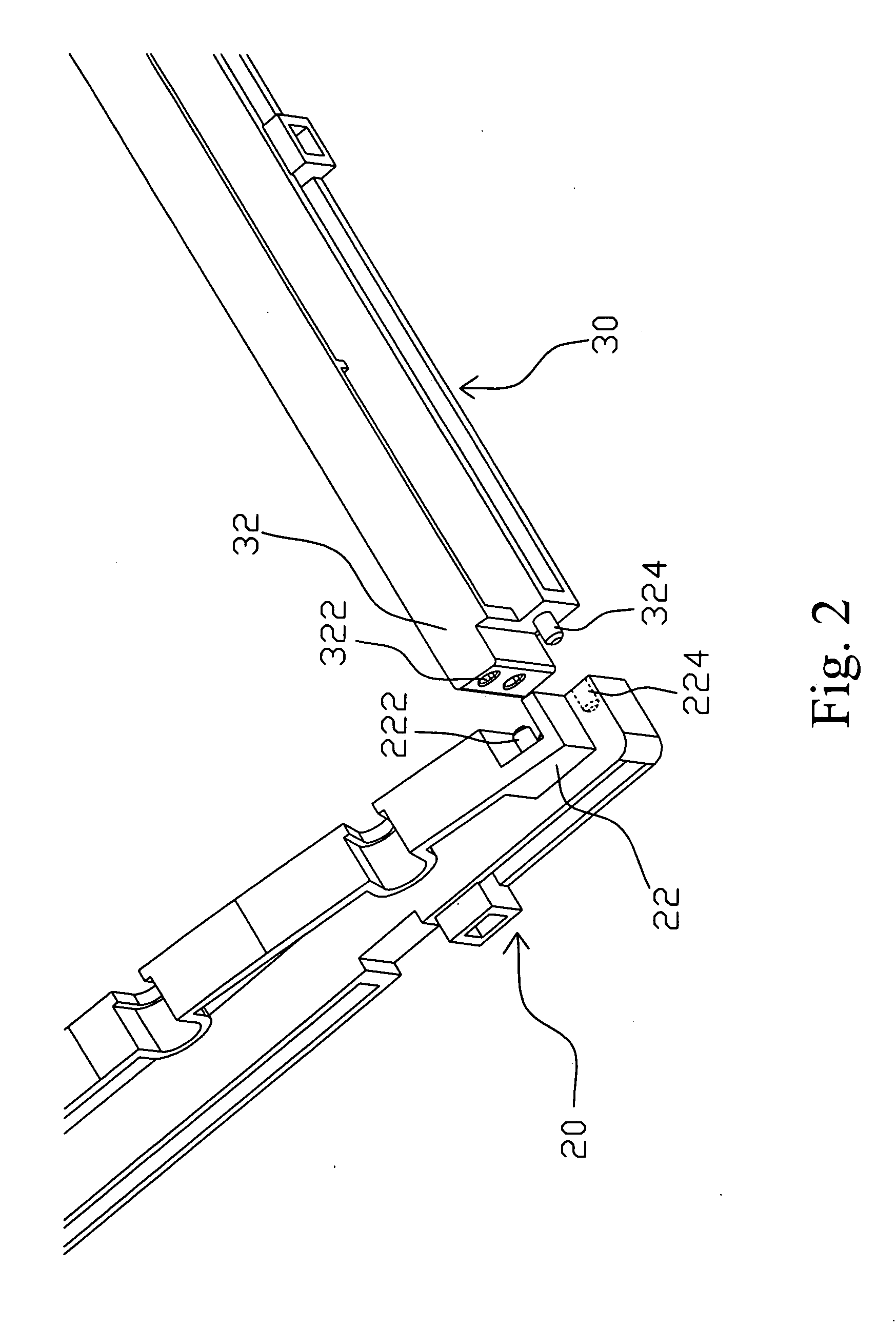
[0018] Please refer to FIG. 1, the complete frame of the back light module 10 is composes of two parallel vertical frames 20 and two parallel horizontal frames 30, and an optical plate 40 is embedded in the frame. Please refer to FIG. 2 and FIG. 3, FIG. 2 and FIG. 3 are assembly structure diagrams according to present invention. Both ends of each horizontal frame 30 are equipped an embedding location 32 composed of two noncircular holes 322 and a pillar 324, and two chutes 34 are set on oppositive surfaces of the two horizontal frames 30; Both ends of the vertical frame 20 also have an embedding location 22 having two pillars 222 and a noncircular hole 224 respectively ...


PUM


Abstract

The invention provides an assembly structure of a back light module having two horizontal frames, two vertical frames and an optical plate. At both ends of each horizontal frame and vertical frame is equipped noncircular holes and pillars, and a plurality of chutes is equipped on the corresponding surfaces of the two horizontal frames to intervene each other for assembling the two horizontal frames and the two vertical frames to a complete frame. The two sides of the optical plate are formed the fixed supports that have a slant corresponding to the chute for installing the optical plate into the complete frame, and the fixed support is embedded into the chute of the horizontal frame. In accordance with the design of embedded structure, the invention can achieve effects of easy assembly, firm structure, low cost and easy disassembling.

Description

BACKGROUND OF INVENTION [0001] 1. Field of the Invention [0002] The invention relates to a back light module, and more particularly, to an assembly structure of a back light module that firmly assembled by interfered conjugation. [0003] 2. Description of the Prior Art [0004] The traditional back light module equips a plurality of lamps at two ends of a frame, and makes the light projecting from two sides into the whole diffusion plate. Since the intensity of the light is getting weaker with the distance, the light intensity at the central part of the diffusion plate is weaker than that at two sides, and the light intensity of the whole diffusion plate is not uniform. Therefore, the back light module of the direct type lamp is developed. The direct type lamp is transversely equipped at the back light position of the diffusion plate in the back light module. When lighting the lamp, the light is uniformly diffused in the diffusion plate without the disadvantage mentioned above. [0005] ...

Claims


Application Information

Patent Timeline
IPC IPC(8): F21V7/04F21V11/00
CPCG02F1/133608G02F1/133604
Inventor WU, SHENG-CHUNLIU, TSUNG-CHENG
Owner CANDLE LAB
Why Eureka
Try Eureka