Methods and apparatus for constructing switch arrays for routing of optical signals so as to minimize power dissipation

a technology of optical signals and switch arrays, which is applied in the direction of electrical apparatus, multiplex system selection arrangements, multiplex communication, etc., can solve the problems of increasing heat generation, power dissipation of arrays, and maximum and average power dissipation, and achieves low power output and high power output.

Inactive Publication Date: 2005-04-21
LUCENT TECH INC
View PDF7 Cites 6 Cited by
  • Summary
  • Abstract
  • Description
  • Claims
  • Application Information

AI Technical Summary

Problems solved by technology

However, minimizing the number of levels of an array typically does not minimize the maximum and average power dissipation of the array, and wavelength independent routing in particular imposes power constraints on the arrays, requiring the worst case and average power dissipated by the array to fall within limits imposed by the desired design of the system in which the array is to be used.
Increasing the power dissipation of an array leads to increased heat generation with the accompanying need to dissipate the heat.
In some cases, it may be necessary for the power dissipation of an array to fall within prescribed power constraints, with these constraints being more stringent if wavelength independent signal routing is to be used.

Method used


Image

  • Methods and apparatus for constructing switch arrays for routing of optical signals so as to minimize power dissipation
  • Methods and apparatus for constructing switch arrays for routing of optical signals so as to minimize power dissipation
  • Methods and apparatus for constructing switch arrays for routing of optical signals so as to minimize power dissipation

Examples


Embodiment Construction

[0019] The present invention will be described more fully hereinafter with reference to the accompanying drawings, in which several presently preferred embodiments of the invention are shown. This invention may, however, be embodied in various forms and should not be construed as limited to the embodiments set forth herein. Rather, these embodiments are provided so that this disclosure will be thorough and complete, and will fully convey the scope of the invention to those skilled in the art.

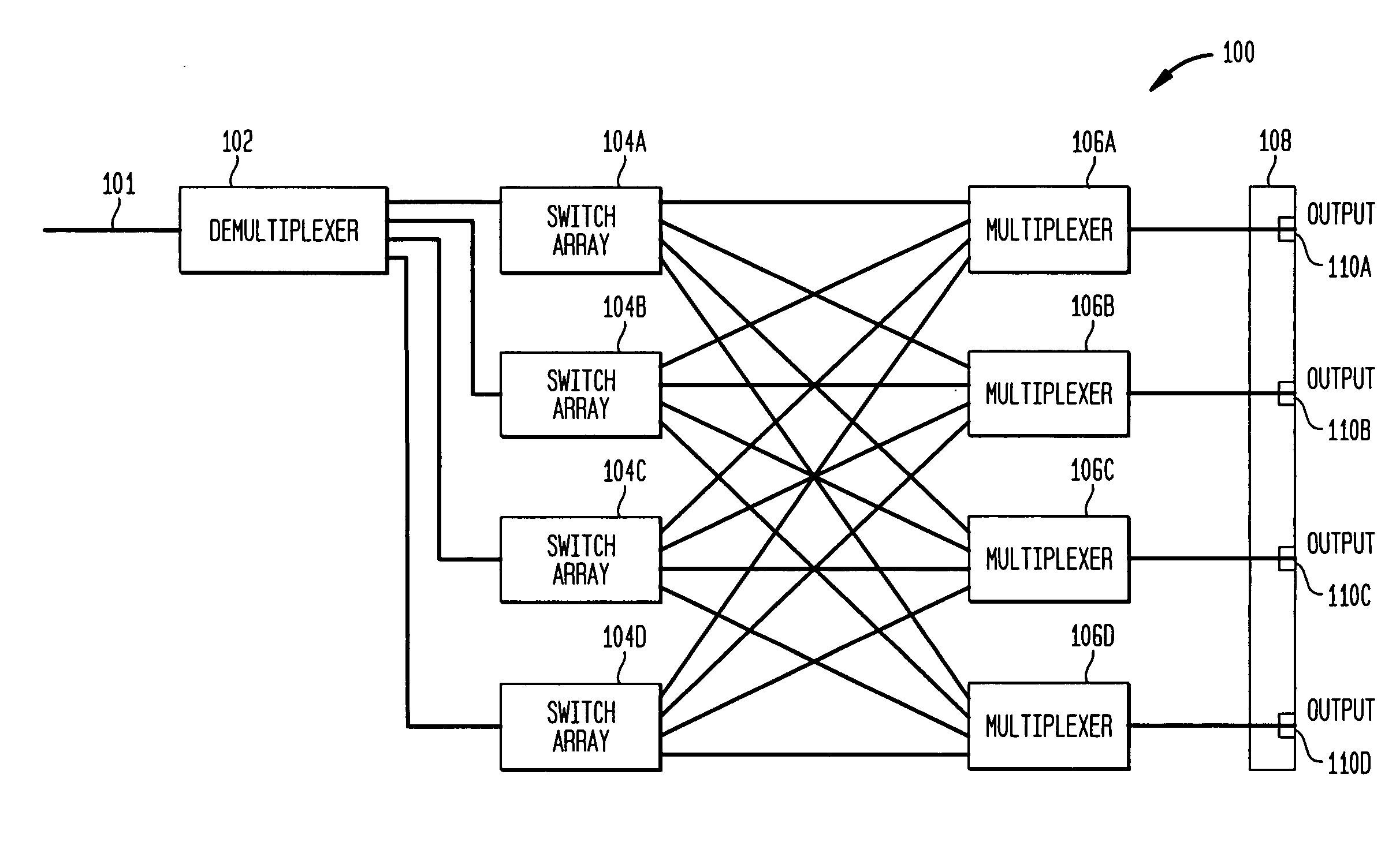
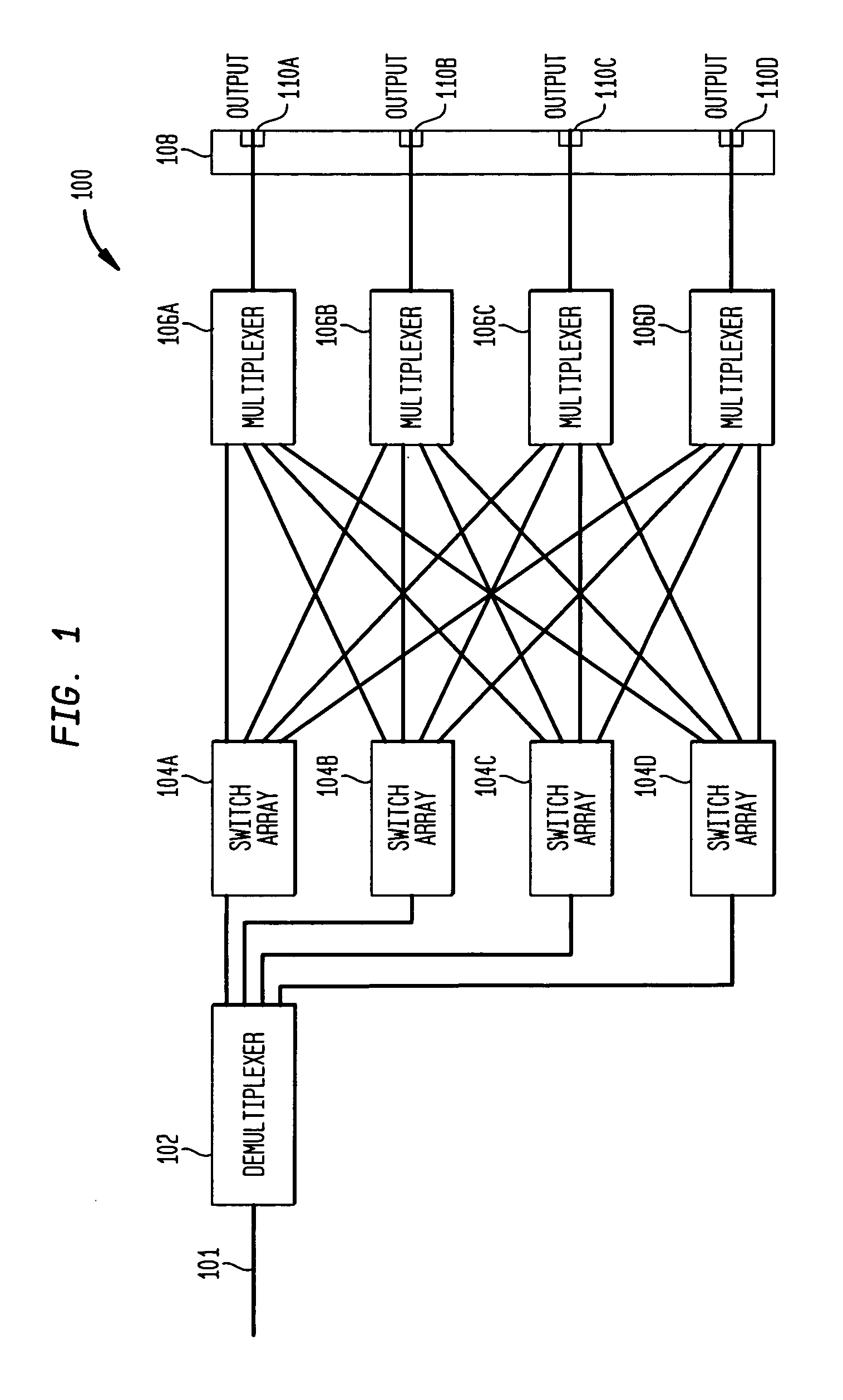
[0020]FIG. 1 illustrates a signal routing system 100 employing switch arrays that may suitably be designed according to the teachings of the present invention. The system 100 includes an input 101 that may suitably be a combined signal comprising a plurality of single wavelength components. The input 101 supplies a demultiplexer 102, which demultiplexes the combined signal and supplies a single wavelength signal to each of four switch arrays 104A-104D. The switch arrays may suitably comprise ar...


PUM


Abstract

Techniques and systems for design of optical switch arrays so as to minimize power requirements are described. A design system includes a computer system hosting a design program. The design program receives parameters for the switch array, including a number N of outputs required, and either a maximum number L of stages allowed or maximum and average power requirements allowed. If power requirements are used as parameters, the design program uses N and the power requirements to compute the value of L. The design program then constructs a minimum power sequence of L switches or N switches, whichever is less. If N is less than L+1, N outputs are present and the array is complete. If N is greater than L+1, the design program then adds switches one at a time to the minimum power switch path of the array, until the array provides N outputs.

Description

FIELD OF THE INVENTION [0001] The present invention relates generally to routing of optical signals. More particularly, the invention relates to construction of switch arrays adhering to depth constraints such that a switch array of a particular depth exhibits minimum power requirements attainable for a switch array of that depth. BACKGROUND OF THE INVENTION [0002] Optical communications are often carried out using a plurality of signals, each signal occupying one of a plurality of wavelengths, with the signals carried by a single optical fiber. Each signal is routed to a desired port through a series of multiplexers and arrays of switches. A fiber carrying a combined signal comprising a number of wavelengths W may be supplied to a routing assembly capable of routing each wavelength to one of a number of outputs N. In some systems, each wavelength will be routed to a single output, with each output carrying a single wavelength. In such a case the number of wavelengths W is equal to ...

Claims


Application Information

Patent Timeline
Patent Type & Authority Applications(United States)
IPC IPC(8): H04Q11/00
CPCH04Q2011/0052H04Q11/0005
Inventor KUMARAN, KRISHNANMURPHY, TIMOTHY O.NITHI, NACHI K.NUZMAN, CARL JEREMYRICHARDS, GAYLORD W.
Owner LUCENT TECH INC
Why Eureka
Try Eureka