Image forming apparatus

a technology of image forming apparatus and forming chamber, which is applied in the direction of electrographic process apparatus, instruments, corona discharge, etc., can solve the problems of image noise generated by the portion of the apparatus, possible creeping of the moving member, and small space inside the apparatus, so as to prevent the generation of image noise

Active Publication Date: 2005-04-21
KONICA MINOLTA BUSINESS TECH INC
View PDF2 Cites 5 Cited by
  • Summary
  • Abstract
  • Description
  • Claims
  • Application Information

AI Technical Summary

Benefits of technology

[0006] Accordingly, an object of the present invention is to provide an image forming apparatus that prevents generation of image noise in such a way that if creep deformation is generated in a movable member having flexibility due to the apparatus being in a high-temperature state while it is being powered-off, the movable member is recovered from the creep deformation when the apparatus is powered on again, before image forming operation is performed, and to provide a control method thereof.

Problems solved by technology

Such movable members possibly suffer creep that is the increase of a strain with a lapse of time under the action of constant external force.
However, the trend of image forming apparatuses in recent years is toward downsizing, and so a space inside the apparatus becomes small.
Consequently, the movable members set in the apparatus are often disposed in the state of having a high deformation degree, which is counted as a disadvantage with respect to creep.
With such a large curvature, creep tends to be generated in a portion of the intermediate transfer belt supported in the state of being curvature-deformed under the action of predefined tension, and when creep deformation is increased, image noise is generated due to that portion.
However, the cooling fan does not function when the apparatus is powered off, which turns out to increase the inside temperature of the apparatus, bringing out an disadvantage with respect to the creep generated in the movable members having flexibility.
Moreover, the apparatus is possibly left under high temperature environments with its power supply cut off for a long period of time while it is transported or stored.

Method used


Image

  • Image forming apparatus
  • Image forming apparatus
  • Image forming apparatus

Examples


Embodiment Construction

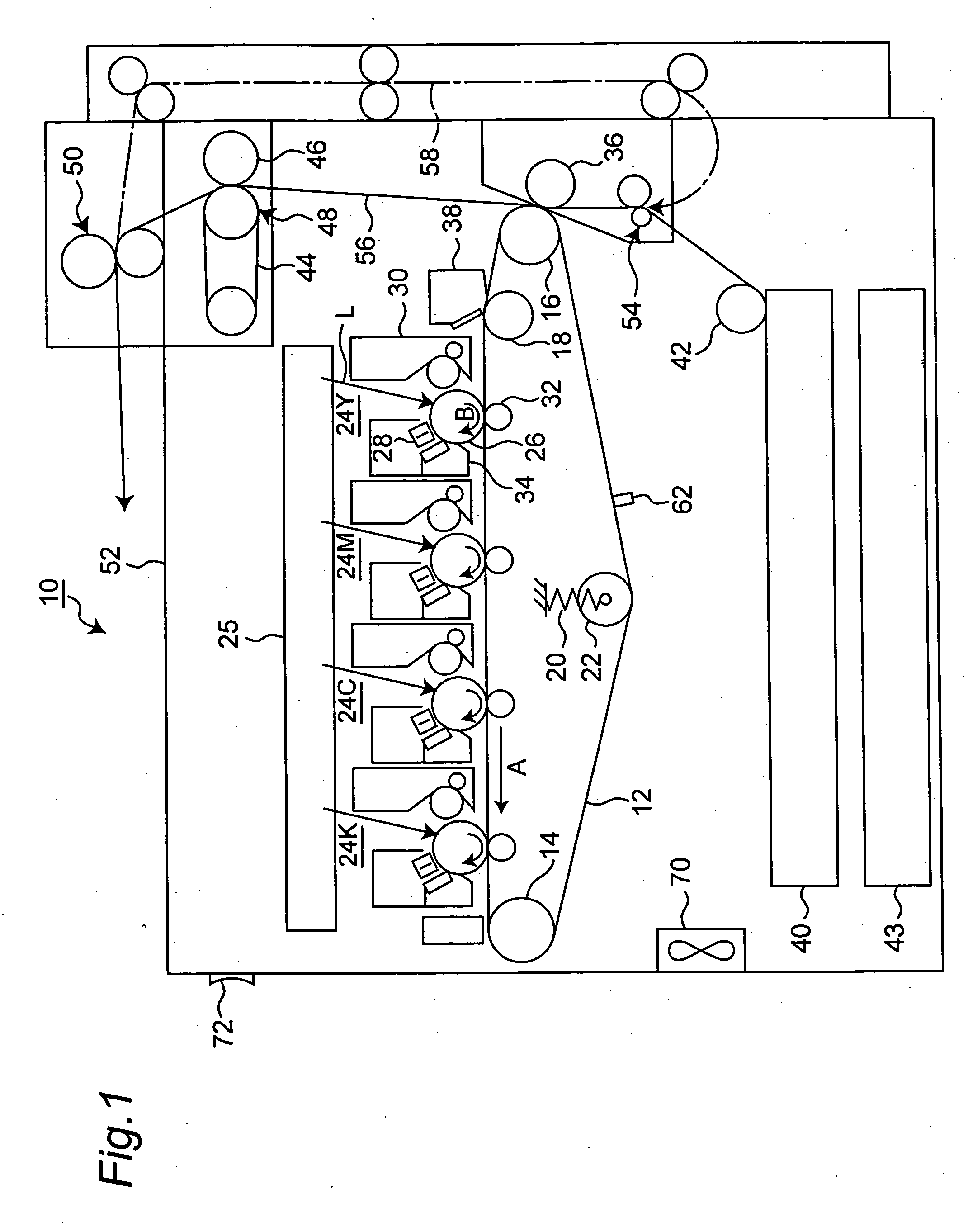
[0036]FIG. 1 shows an overall configuration of an image forming apparatus 10 in one embodiment of the present invention. The image forming apparatus 10 is equipped with an intermediate transfer belt 12 that is an movable member having flexibility situated in an almost center section of the apparatus. The intermediate transfer belt. 12 is composed of an endless belt made of a thin resin film.

[0037] The intermediate transfer belt 12 is hung over three support rollers 14, 16, 18 that are provided inside of the intermediate transfer belt 12. A tension roller 20 pressed by a spring 20 is in press-contact with the intermediate transfer belt 12 from inside, so that the intermediate transfer belt 12 is under the action of a specified tension (i.e., external force). Thus, the intermediate transfer belt 12 is in an inoperative state with the roller-supported portions being curved under the action of the specified tension when image forming is not under operation. Further, the support roller ...


PUM


Abstract

To provide an image forming apparatus that prevents generation of image noise by recovering a movable member having flexibility from creep deformation. The image forming apparatus for forming images on a recording medium comprises a movable member having flexibility, a detection section for detecting temperature of the movable member directly, a storage section for storing the temperature detected by the detection section when the apparatus is powered off, and a control section for changing a duration of time during which the movable member is in a preparatory operation corresponding to the detected temperature read from the storage section when the apparatus is powered on.

Description

RELATED APPLICATION [0001] This application is based on Japanese Patent Application No. 2003-359004, the content of which is incorporated herein by reference. BACKGROUND OF THE INVENTION [0002] The present invention relates to an image forming apparatus capable of preventing generation of image noise by making recovery from creep deformation of movable members having flexibility such as intermediate transfer belts for use in copying machines and printing machines. [0003] In image forming apparatuses such as copying machines and printing machines, movable members having flexibility such as intermediate transfer belts have conventionally been used. Such movable members possibly suffer creep that is the increase of a strain with a lapse of time under the action of constant external force. The creep has dependence on curvature deformation degree, temperature, curvature deformation state retention time, and material properties of the movable members. Accordingly, in order to prevent the ...

Claims


Application Information

Patent Timeline
Patent Type & Authority Applications(United States)
IPC IPC(8): G03G21/14G03G15/00G03G15/02G03G15/16G03G15/20
CPCG03G15/5054
Inventor YOSHIDA, NARUTAKA
Owner KONICA MINOLTA BUSINESS TECH INC
Why Eureka
Try Eureka