Ribbon cassette for thermal transfer printer

a thermal transfer printer and cassette technology, applied in printing mechanisms, inking apparatus, printing, etc., can solve the problems of ink ribbon creases due to meandering, and achieve the effect of preventing the creasing or meandering of the ink ribbon during printing, and reliably guiding the ink ribbon

Inactive Publication Date: 2005-04-21
ALPS ALPINE CO LTD
View PDF12 Cites 4 Cited by
  • Summary
  • Abstract
  • Description
  • Claims
  • Application Information

AI Technical Summary

Benefits of technology

[0022] As second means for achieving the above objects, a portion of the meandering preventing portion, which is to be brought into slidably contact with a widthwise middle portion of the ink ribbon, is bulged nearer toward the supply core than portions of the meandering preventing portion, which are to be brought into slidably contact with both widthwise ends of the ink ribbon. By this feature having the meandering preventing portion, a tensile force is induced in the ink ribbon to stretch the ink ribbon in a widthwise direction, whereby it is possible to prevent the ink ribbon from creasing or meandering during printing.
[0023] As third means for achieving the above objects, the portion of the meandering preventing portion, which is to be brought into slidably contact with the widthwise middle portion of the ink ribbon, is bulged toward the supply core in such a way as to define an arc-shaped contour. By this feature, it is possible to more reliably prevent the ink ribbon from creasing or meandering during printing.
[0024] As fourth means for achieving the above objects, the ribbon cassette further comprises a guide shaft having both longitudinal ends which are rotatably fitted into first and second holes formed in the cassette case adjacent to the winding core with respect to the opening, to guide the path of the ink ribbon. By this feature, even when the ribbon cassette is inadvertently dropped to the floor, the guide shaft is prevented from being separated from the cassette case, whereby the guide shaft can reliably guide the ink ribbon.
[0025] As fifth means for achieving the above objects, the first hole is formed through a first wall portion which is formed to protrude on the cassette case and has a predetermined thickness; the second hole is formed through a second wall portion formed opposite to the first wall portion so as to face the first hole; and the guide shaft is rotatably supported in the first and second holes by having its one end inserted in one direction through the first hole to project out of the first hole, and having the other end placed on the cassette case adjacent to the second hole and then sled in a direction to be fitted into the second hole. By this feature, the assembling process can be improved when attaching the guide shaft to the cassette case.
[0026] As sixth means for achieving the above objects, a guide groove for guiding the other end of the guide shaft into the second hole is formed in the cassette case, adjacent to the second hole, on which the other end of the guide shaft is placed. By this feature, the other end of the guide shaft can be reliably guided to be inserted into the second hole, more effectively, which further improves the assembly process.
[0027] As seventh means for achieving the above objects, the cassette case is provided with a first cover for covering an upper portion of the supply core and a second cover for covering an upper portion of the winding core; and a regulating portion, which abuts on one end of the guide shaft fitted into the first hole to regulate the axial movement of the guide shaft, is formed on the second cover. By this feature, it is possible to effectively prevent the guide shaft from being unintentionally separated from the cassette case.

Problems solved by technology

As a result, creases due to the meandering are not made in the ink ribbon.

Method used


Image

  • Ribbon cassette for thermal transfer printer
  • Ribbon cassette for thermal transfer printer
  • Ribbon cassette for thermal transfer printer

Examples


Embodiment Construction

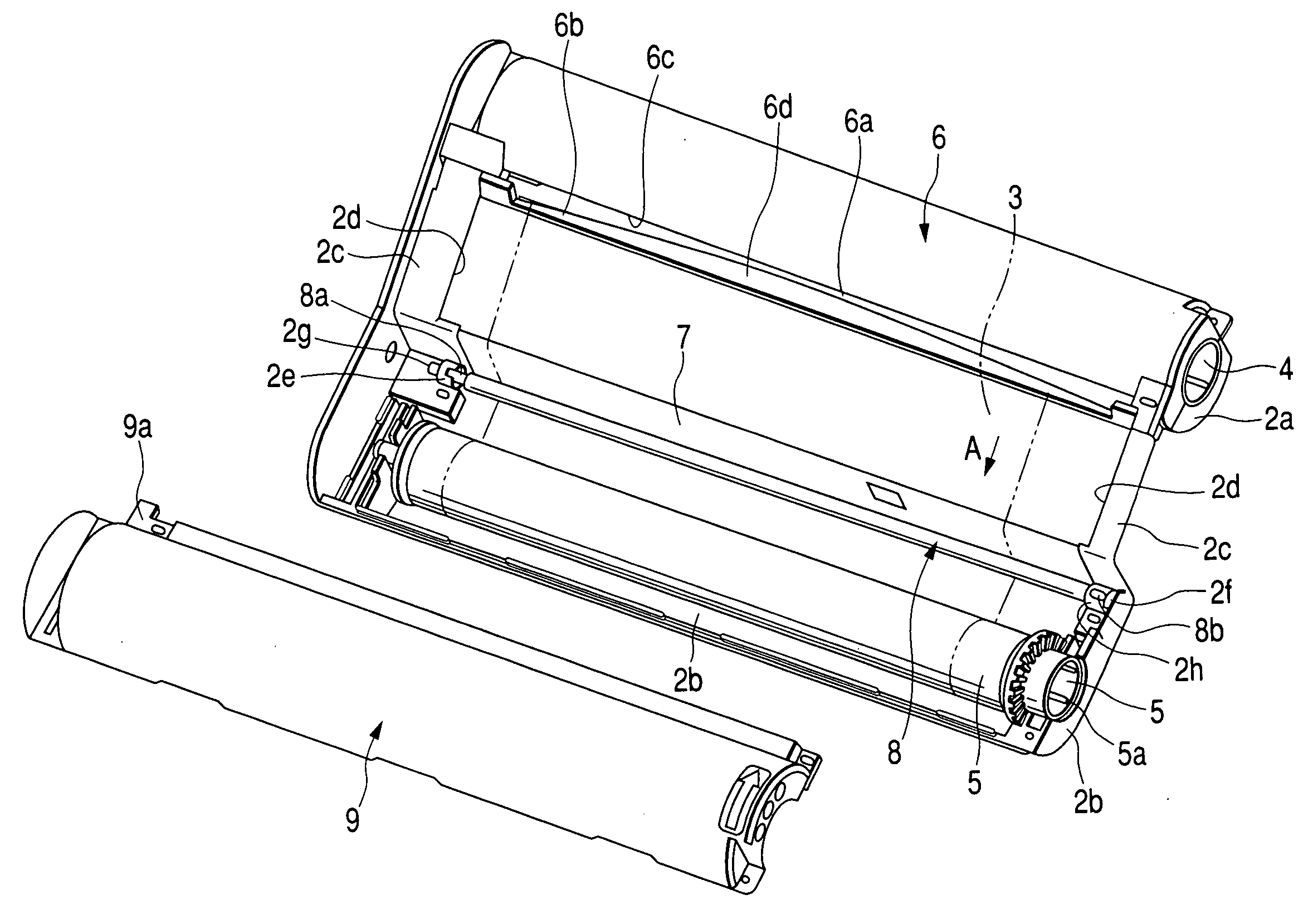
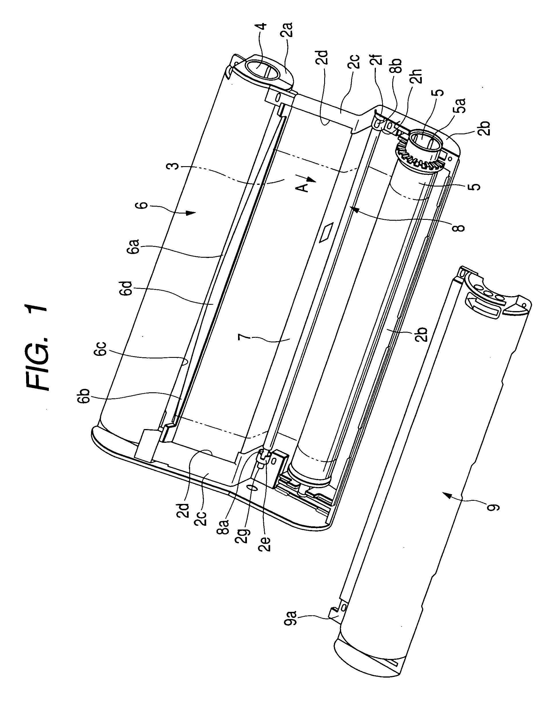
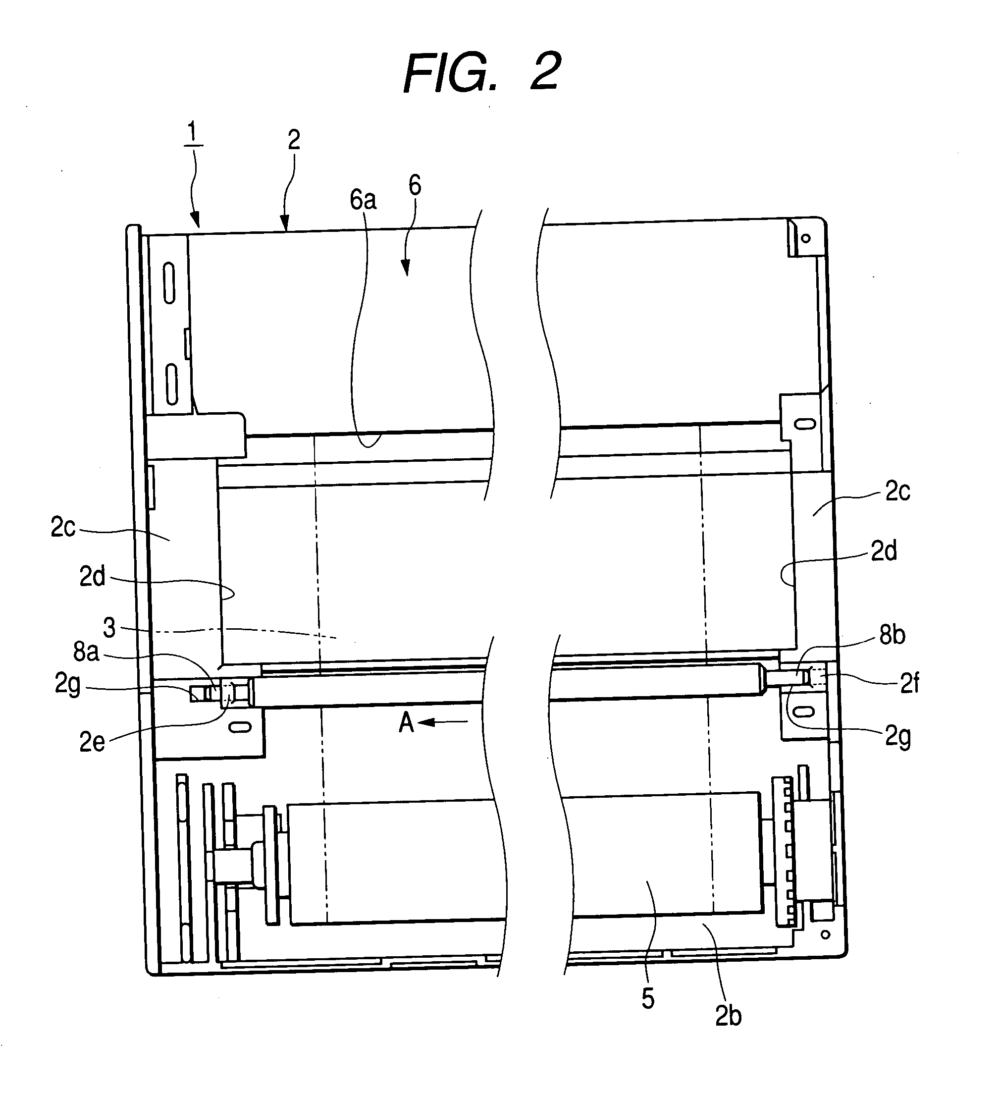
[0033] Hereinafter, a ribbon cassette 1 according to an embodiment of the present invention will be described with reference to the drawings. FIG. 1 is an exploded perspective view illustrating the ribbon cassette according to the present invention; and FIGS. 2 to 4 are plan views explaining an assembling procedure of the ribbon cassette according to the present invention.

[0034] First, referring to FIG. 1, the ribbon cassette 1 according to the embodiment of the present invention has a cassette case 2 which has a sideways long configuration and is made of a resinous material. A wide ink ribbon 3 as shown by the two-dot chain lines is laid in the cassette case 2. Ink is applied on a face of the ink ribbon 3, and both ends of the ink-ribbon 3 are wound around a supply core 4 and a winding core 5.

[0035] The supply core 4 is rotatably supported by a first core support portion 2a which is formed in the cassette case 2. The winding core 5 is rotatably supported by a second core support ...


PUM


Abstract

A ribbon cassette contains an ink ribbon, a supply core and winding core around which ends of the ink ribbon are wound, a cassette case for rotatably supporting the supply rewinding cores, and a ribbon guide part guiding the path of the ink ribbon. The ink ribbon guide part is a meandering preventing portion constructed such that a portion of the ink ribbon guide part to be brought into slidable contact with a widthwise middle portion of the ink ribbon is wider than portions to be brought into slidable contact with widthwise ends of the ink ribbon. Further, by fitting both ends of a guide shaft for guiding the ink ribbon into first and second holes formed in first and second wall portions formed on the cassette case, the guide shaft 8 is rotatably supported in the first and second holes.

Description

BACKGROUND OF THE INVENTION [0001] 1. Field of the Invention [0002] The present invention relates to a ribbon cassette used in a thermal transfer printer, and more particularly, to a ribbon cassette for a thermal transfer printer which has a ribbon guide section capable of guiding the travel of an ink ribbon supplied from a supply core to be wound around a winding core. [0003] 2. Description of the Related Art [0004] A conventional ribbon cassette used in a thermal transfer printer such as a photo printer capable of high-precision printing, and the like, has a construction as shown in FIG. 5. [0005] Referring to FIG. 5, a conventional ribbon cassette 21 typically has a cassette case 22 formed of a resinous material, and a wide and lengthened ink ribbon 23 as shown by the two-dot chain lines is laid in the cassette case 22. [0006] The ink ribbon 23 is wound around a supply core 24 and a winding core 25. The supply core 24 and the winding core 25 are received in and rotatably supporte...

Claims


Application Information

Patent Timeline
Patent Type & Authority Applications(United States)
IPC IPC(8): B41J17/32
CPCB41J17/32
Inventor FUNAKI, HITOSHITOKUTA, SHIGETO
Owner ALPS ALPINE CO LTD
Why Eureka
Try Eureka