Card adapter

a card adapter and card technology, applied in the direction of electric discharge lamps, coupling device connections, electric discharge tubes, etc., can solve the problems of too complex production process to reduce production costs, and achieve the effects of reducing production costs and production processes, simplifying the structure of combinations, and simplifying production processes

Inactive Publication Date: 2005-04-21
TAI SOL ELECTRONICS
View PDF1 Cites 11 Cited by
  • Summary
  • Abstract
  • Description
  • Claims
  • Application Information

AI Technical Summary

Benefits of technology

[0007] The primary objective of the present invention is to provide a card adapter that simplifies the structure of combination of the card connector and the card adapter to further simplify the production process.
[0008] The secondary objective of the present invention is to provide a card adapter which production cost and production process are lower and simpler than the prior art.
[0009] The foregoing objectives of the present invention are attained by the card adapter that is composed of a frame member, two cover plates, an internal frame, an adapting circuit board, and a terminal connector. The frame member includes an insertion slot at a front end thereof. The two cover plates are covered on the frame member. The internal frame is disposed inside the frame member and includes a plurality of terminals, a lateral section and a rear section that both define a reception space together with a front edge and a lateral edge of the frame member. Two guide grooves are respectively disposed on the lateral edge of the frame member and the lateral section of the internal frame. The adapting circuit board includes a plurality of electronic components formed as an adapting control circuit electrically connected with the terminals of the internal frame. The terminal connector is mounted at a rear end of the frame member and is connected with the adapting circuit board. Accordingly, the card adapter of the present invention is structurally simplified and low in production cost.

Problems solved by technology

However, the aforementioned conventional arrangement includes some drawbacks.
In addition, the card connector has to be secured inside the adapter by adhesives or clamping tools, substantially requiring four steps to complete the combination of the card connector and the adapter, such that the production process is too complex to reduce the production cost.

Method used


Image

  • Card adapter
  • Card adapter
  • Card adapter

Examples


Embodiment Construction

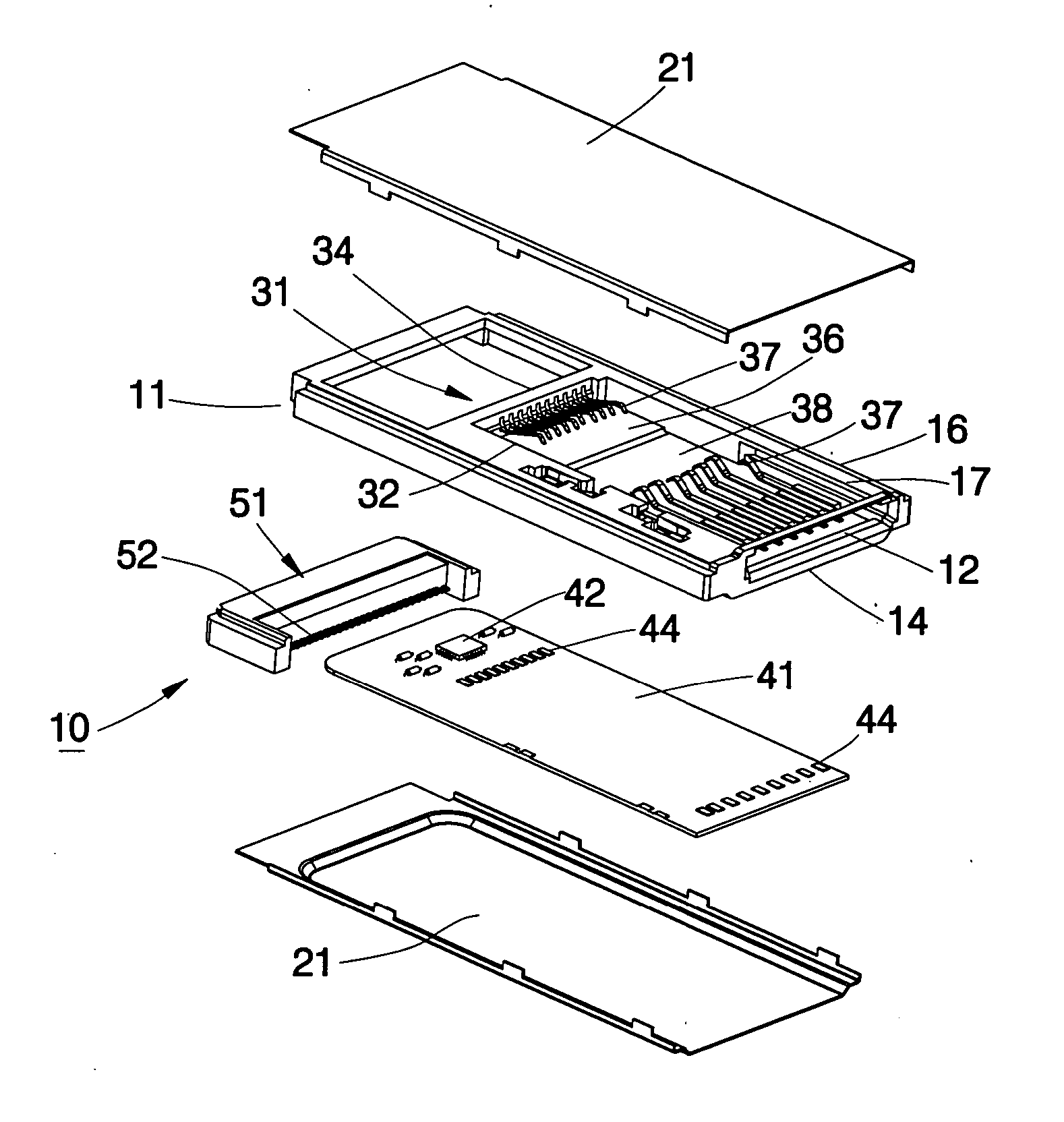
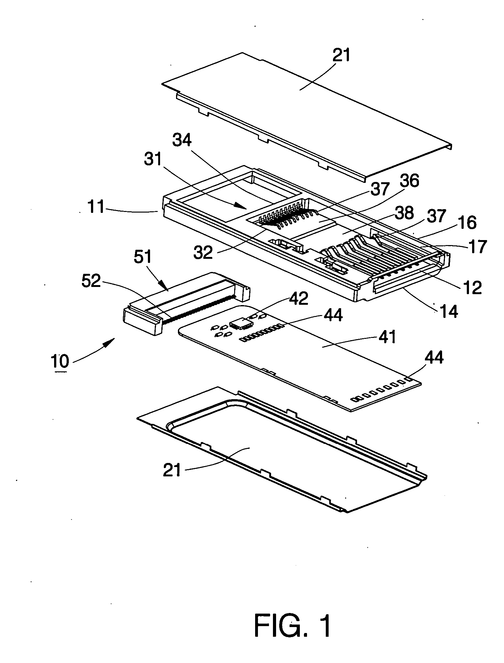
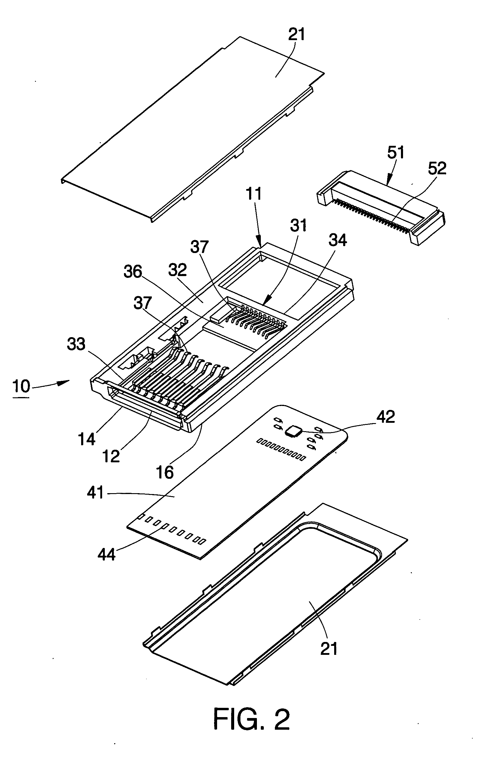
[0018] Referring to FIGS. 1-4, a card adapter 10 constructed according to a first preferred embodiment of the present invention is composed of a frame member 11, two cover plates 21, an internal frame 31, an adapting circuit board 41, and a terminal connector 51.

[0019] The frame member 11 includes an insertion slot 12 at a front end thereof.

[0020] The two cover plates 21 are respectively covered on a top side and a bottom side of the frame member 11.

[0021] The internal frame 31 is disposed inside and integrally formed with the frame member 11 and includes a lateral section 32 and a rear section 34, which both together with a front edge 14 and a lateral edge 16 of the frame member 11 define a reception space 38. Two guide grooves 17 and 33 are respectively disposed on the front edge 14 of the frame member 11 and the lateral section 32 of the internal frame 31. The insertion slot 12 of the frame member 11 is positioned at a front end of the reception space 38. The two guide grooves...


PUM


Abstract

A card adapter for accommodating a memory card and connecting an external device is composed of a frame member, two cover plates covered on the frame member, an internal frame disposed inside the frame member and having a plurality of terminals, a lateral section and a rear section that both define a reception space together with a front edge and a lateral edge of the frame member, two guide grooves respectively disposed on the lateral edge of the frame member and the lateral section of the internal frame, an adapting circuit board electrically connected with the terminals of the internal frame, and an terminal connector mounted at a rear end of the frame member and is connected with the adapting circuit board. Accordingly, the card adapter of the present invention is structurally simplified and low in production cost.

Description

BACKGROUND OF THE INVENTION [0001] 1. Field of the Invention [0002] The present invention relates generally to electronic devices, and more particularly to a card adapter for accommodating a memory card and connecting an external device. [0003] 2. Description of the Related Art [0004] A conventional card connector is different from personal computers (PC) and other electronic devices in design, size, and interface, such that an adapter is required to interface between the card connector and other devices. [0005] As shown in FIG. 8, when a card connector is connected to an adapter by a conventional way, the card connector 81 is put into the adapter 86, the card connector 81 is fixedly adhered or clamped into the adapter 86, an adapting circuit board 87 is connected with contact pins of the card connector 81, the contact pins of the card connector 81 are converted by the adapter 86, a control circuit 88 of the adapting circuit board 87 is used to accommodate a predetermined interface,...

Claims


Application Information

Patent Timeline
Patent Type & Authority Applications(United States)
IPC IPC(8): H01R31/06
CPCH01R31/065Y10S439/945H01R12/714H01R12/721
Inventor LAI, YAW-HUEY
Owner TAI SOL ELECTRONICS
Why Eureka
Try Eureka