Railway pier and beam combining structure suitable for multi-span long coupling and large expansion and contraction quantity beams on two sides

A technology of expansion and contraction, which is applied in the direction of bridges, bridge parts, bridge construction, etc., can solve problems such as poor ride comfort, too large bridge piers, and low bridge rigidity, and achieve strong terrain adaptability, improved overall layout, and good adaptability Effect

Pending Publication Date: 2018-11-13
CHINA RAILWAY SIYUAN SURVEY & DESIGN GRP
View PDF6 Cites 2 Cited by
  • Summary
  • Abstract
  • Description
  • Claims
  • Application Information

AI Technical Summary

Problems solved by technology

[0006] The purpose of the present invention is to solve the problems of the existing long-span long-span bridge mentioned in the above background technology that the pier is too large, the bridge rigidity is low, and the ride comfort is poor, and to provide a bridge pier suitable for long-connected large-span railway bridges on both sides. beam bonded structure

Method used


Image

  • Railway pier and beam combining structure suitable for multi-span long coupling and large expansion and contraction quantity beams on two sides
  • Railway pier and beam combining structure suitable for multi-span long coupling and large expansion and contraction quantity beams on two sides
  • Railway pier and beam combining structure suitable for multi-span long coupling and large expansion and contraction quantity beams on two sides

Examples


Embodiment Construction

[0019] The present invention will be further described in detail below in conjunction with the accompanying drawings and specific embodiments.

[0020] To build a flat road-rail bridge in a certain place, the bridge includes a long-connected large-scale beam section structure with a length of 400-600m, and according to the existing technology, the long-linked large-scale beam section is transitioned by building a transition span containing two piers There are problems of too many piers and high cost. This embodiment provides a new type of transition structure connecting long-connected and large-scale beams on both sides.

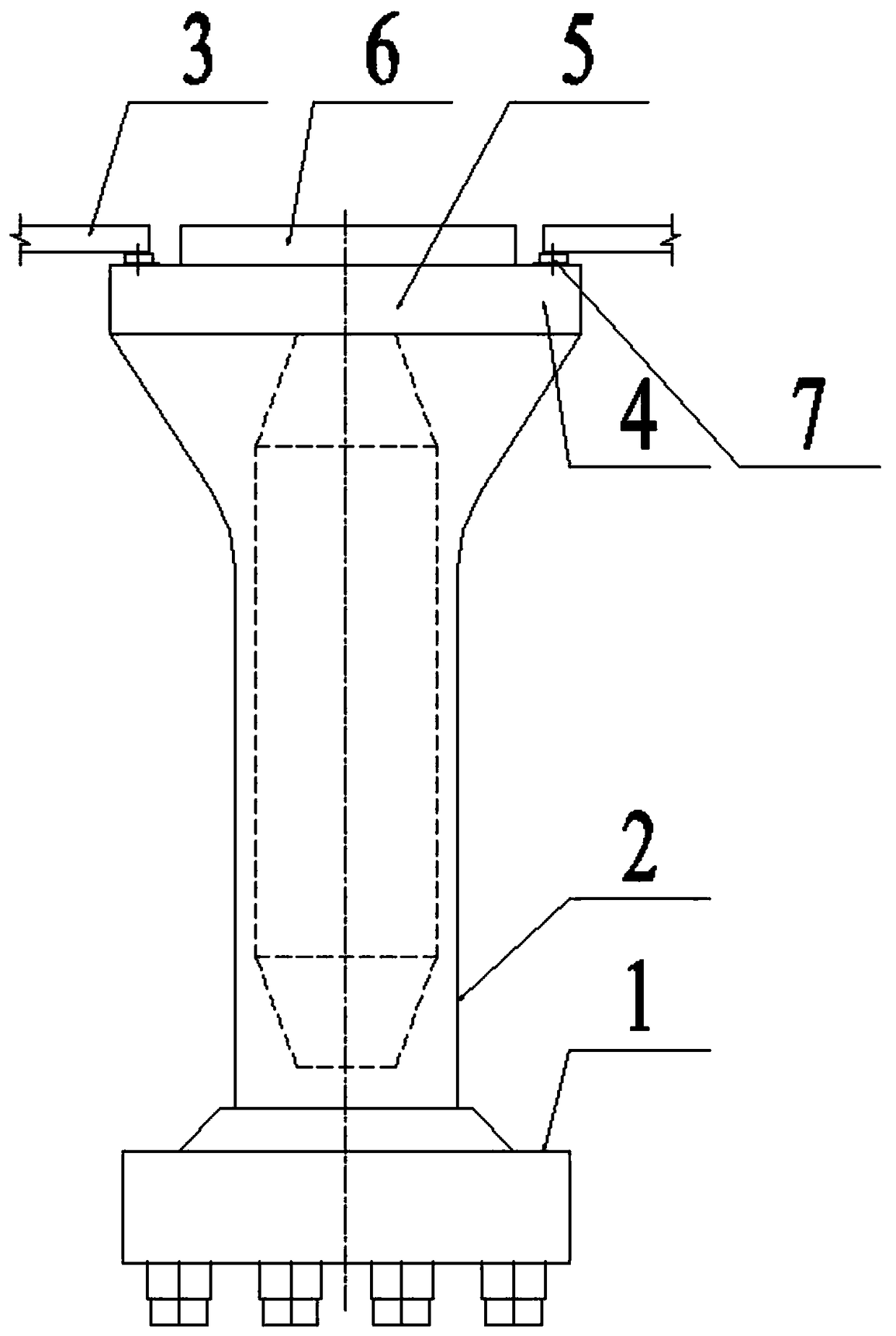
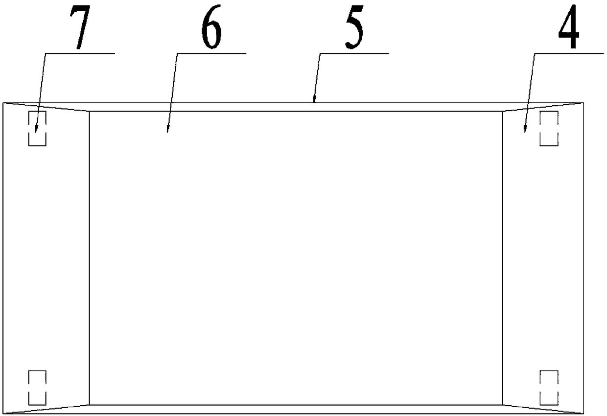
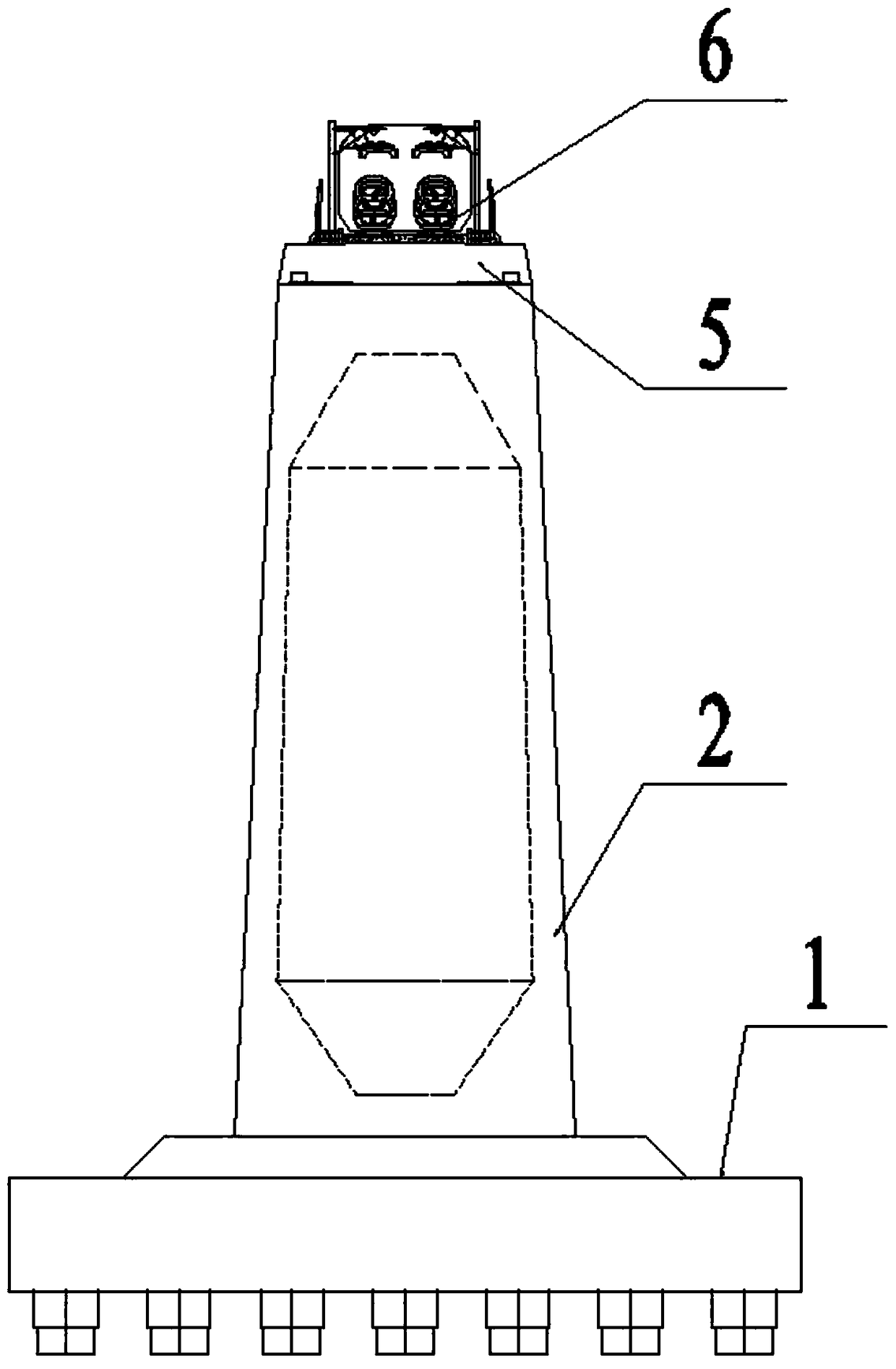
[0021] Such as Figure 1~3 , a pier-beam combination structure suitable for railway bridges with long-connected and large-scale expansion on both sides. The joint expansion beam 3 includes a cap 1 and a bridge pier 2 located on the cap 1 , and a pier-beam joint section and a beam portion 6 are arranged on the bridge pier 2 .

[0022] Such as figure 1 As s...


PUM


Abstract

The invention relates to the technical field of bridge structures, in particular to a railway pier and beam combining structure suitable for multi-span long coupling and large expansion and contraction quantity beams on two sides. The railway pier and beam combining structure comprises a bearing platform and a pier located on the bearing platform, and is characterized by further comprising a pierand beam combining section and a beam part; the pier and beam combining section is of a reinforced concrete structure which is fixed at the upper end of the pier in a pouring mode, the pier and beam combining section comprises beam section supporting parts and a beam part supporting part, wherein the beam section supporting parts are located at the two ends in the bridge direction and used for bearing the multi-span long coupling and large expansion and contraction quantity beams on two sides, and the beam part supporting part is located in the middle and used for bearing the beam part; the beam part is fixed on the beam part supporting part and is used for connecting the multi-span long coupling and large expansion and contraction quantity beams on two sides, and expansion joints are reserved between the two ends of the beam part in the bridge direction and the multi-span long coupling and large expansion and contraction quantity beams on two sides. According to the pier and beam combining structure, a series of problems of continuous arrangement of the multi-span long coupling and large expansion and contraction quantity beams are solved skillfully through a series of measures, the overall arrangement of bridge hole spans is effectively improved, the structure stress is reasonable and safe, economic benefits are good, and the railway pier and beam combining structure is a structural form worthy of being widely popularized.

Description

technical field [0001] The invention relates to the technical field of bridge structures, in particular to a pier-beam combination structure suitable for railway bridges with long joints on both sides and large expansion and contraction. Background technique [0002] For bridge positions with large span requirements, spanning a wide range of waters, and deep water depths, foundation works often account for more than half of the total investment, and the number of pier installations in the water must be reduced as much as possible. The current conventional hole-span arrangement in this area is difficult to apply, and the continuous arrangement of long-connected and large-span bridges is often required. In the railway bridge or highway-rail level bridge project, the problems of adopting this layout form are that the continuous setting of long-span bridges leads to long temperature spans, difficult setting of rail temperature expansion and expansion regulators, and superpositio...

Claims


Application Information

Patent Timeline
Patent Type & Authority Applications(China)
IPC IPC(8): E01D19/02E01D19/00E01D19/06
CPCE01D19/00E01D19/02E01D19/06
Inventor 文望青严爱国曾敏王鹏宇李桂林崔苗苗黄振李的平史娣尹书军张晓江周刚郭安娜周继
Owner CHINA RAILWAY SIYUAN SURVEY & DESIGN GRP
Why Eureka
Try Eureka