

Self-piercing rivet setting die and apparatus
- Summary
- Abstract
- Description
- Claims
- Application Information
AI Technical Summary
Benefits of technology
Problems solved by technology
Method used
Image

Examples
example 1
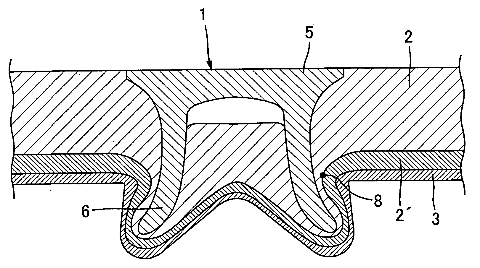
[0066]FIG. 9 is a sectional view illustrating the state where the workpieces 2 and 3 are connected by the self-piercing rivet 1 using the die 18 according to the present invention. In Example 1, due to the shape of the cavity 25 of the die 18, the material of the workpieces flows well within the cavity 25. The receiving-side workpiece 3 has the squeezed configuration in the upper part of the cavity thereby creating the undercut, and thus the workpieces are reliably connected. As a result, the thick workpiece 2 and the thin receiving-side workpiece 3 are not easily separated.
example 2
[0069]FIG. 11 is a sectional view illustrating the state where three workpieces 2, 2′, and 3 are connected by the self-piercing rivet 1 using the die according to the present invention. In Example 2, the receiving-side workpiece 3 is squeezed at the upper part of the cavity and thus the undercut is formed. Therefore, after the workpieces are connected, the receiving-side workpiece will not separate from the interface therebetween.
[0070] As described above, when the workpieces are connected by the self-piercing rivet using the die according to the present invention, a smooth flow of the material of the workpieces can be formed upon connecting the workpieces, and as a result the receiving-side workpiece has the squeezed configuration in the upper part of the cavity, thereby creating the undercut. Therefore, the workpieces can be connected more reliably than the case where the self-piercing rivet connects the workpieces using the conventional die.
[0071] In particular, when the receiv...
PUM
| Property | Measurement | Unit |
|---|---|---|
| Angle | aaaaa | aaaaa |
| Thickness | aaaaa | aaaaa |
| Diameter | aaaaa | aaaaa |
Abstract
Description
Claims
Application Information