

Vibration isolating handle
a technology of vibration isolating handle and handle, which is applied in the direction of portable power-driven tools, drilling machines, manufacturing tools, etc., can solve the problems of inability to obtain varies in vibration reducing effectiveness, and achieve the effect of stable vibration reducing effectiveness
- Summary
- Abstract
- Description
- Claims
- Application Information
AI Technical Summary
Benefits of technology
Problems solved by technology
Method used
Image

Examples
first representative embodiment
(First Representative Embodiment)
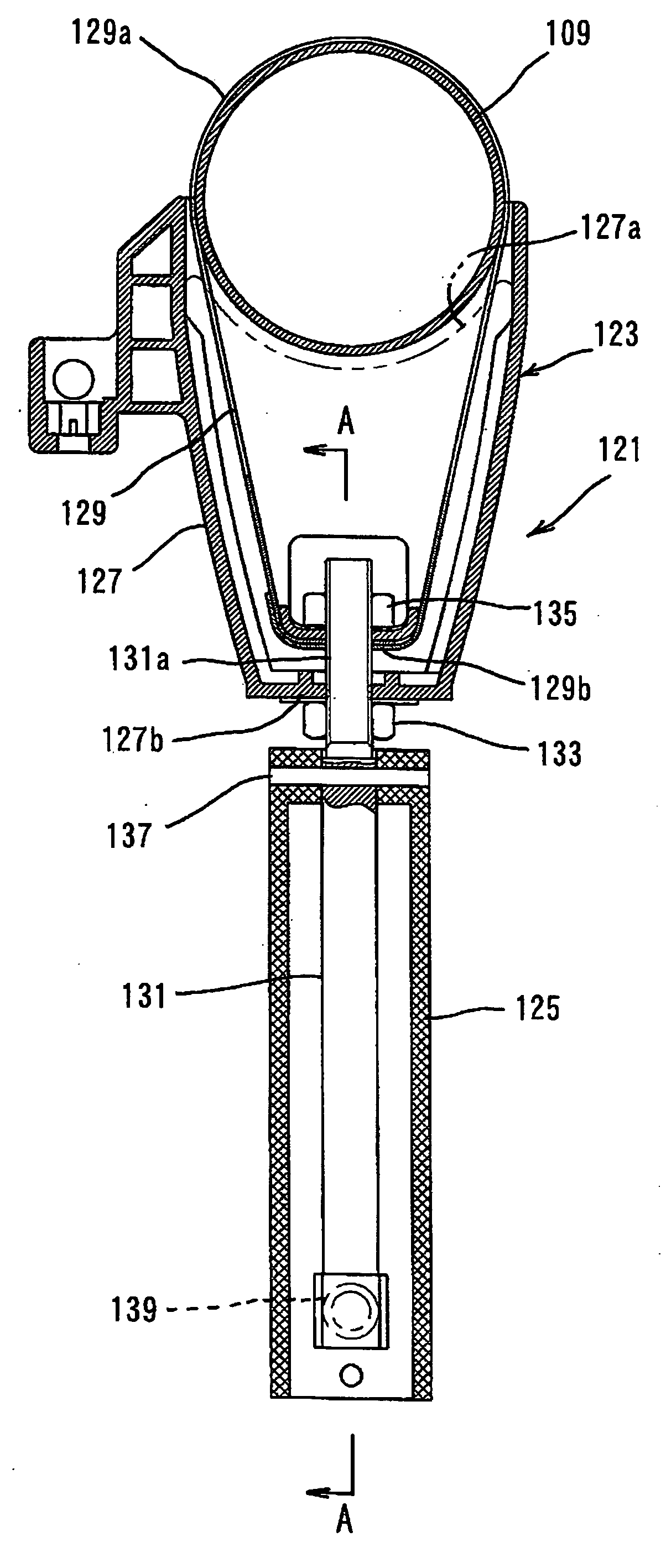
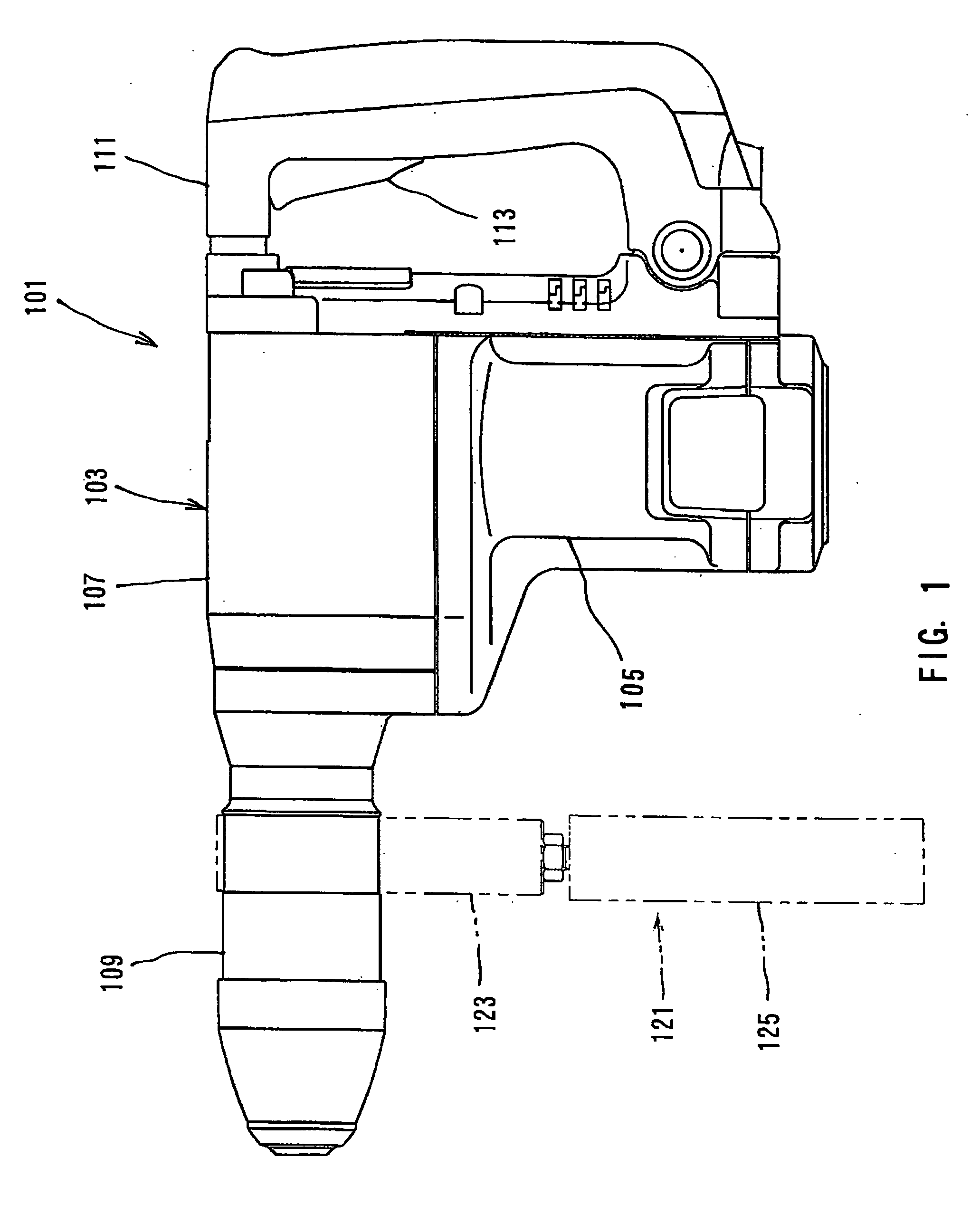
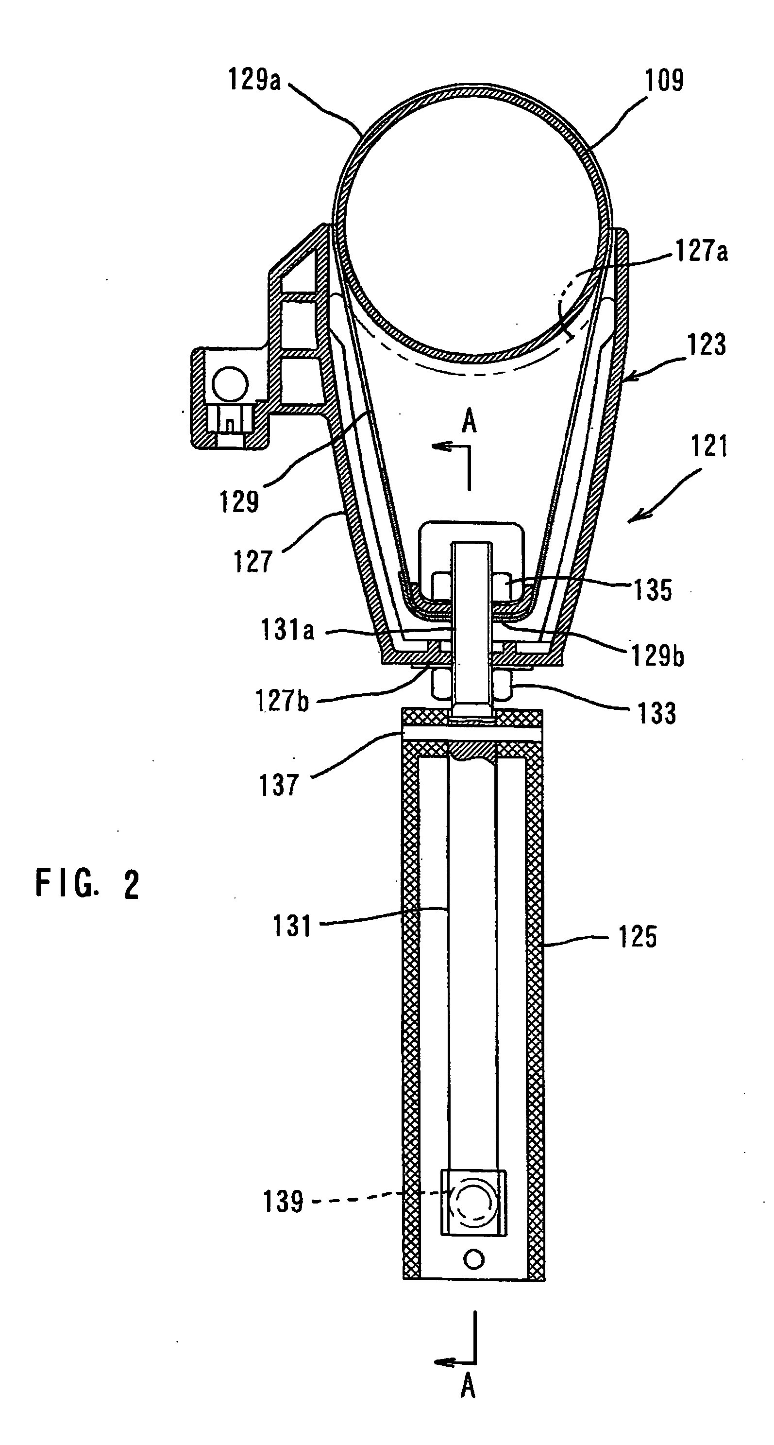
[0034] An embodiment of the present invention will now be described with reference to the drawings. The embodiment of the present invention will be explained as to a vibration isolating handle when applied as an auxiliary handle for operating an electric hammer which is a representative example of a reciprocating power tool. FIG. 1 shows the entire auxiliary handle attached to an electric hammer, by phantom line. FIGS. 2 and 3 show the auxiliary handle in vertical section. Further, FIGS. 4 and 5 show part of the auxiliary handle in cross section.
[0035] First, an electric hammer 101 to which an auxiliary handle 121 is attached will be explained briefly with reference to FIG. 1. The electric hammer 101 mainly includes a body 103 which defines the contours of the electric hammer 101. The body 103 is a feature that corresponds to the “power tool body” according to the present invention. The body 103 includes a motor housing 105, a gear housing 107 and a...
second representative embodiment
(Second Representative Embodiment)
[0060] Second representative embodiment of the present invention will now be described with reference to FIGS. 6 to 11. FIG. 6 shows the entire auxiliary handle attached to an electric hammer, by phantom line. FIGS. 7 and 8 show the auxiliary handle in vertical section. Further, FIGS. 9 to 11 show part of the auxiliary handle in cross section.
[0061] The electric hammer 201 mainly includes a body 203 which defines the contours of the electric hammer 201. The body 203 is a feature that corresponds to the “power tool body” according to the present invention. The body 203 includes a motor housing 205, a gear housing 207 and a tool holder (barrel part) 209 which occupies the tip end (front end) region of the gear housing 207. A main handle (handgrip) 211 is mounted on the rear end of the motor housing 205 and the gear housing 207.
[0062] The auxiliary handle 221 includes a handle body 223 and a grip part 225. The handle body 223 is removably attached to...
fourth representative embodiment
(Fourth Representative Embodiment)
[0080] A vibration insulating handle according to fourth embodiment of the present invention will now be described with reference to FIGS. 17 to 19. The vibration insulating handle according to this embodiment is suitably applied as an auxiliary handle to a rotary power tool that performs an operation on a workpiece by rotating a tool bit. The rotary power tool embraces a power tool such as a grinder, a circular saw and a vibratory drill, in which vibration is caused in varying directions. Representative auxiliary handle 461 according to this embodiment includes a handle body in the form of a cylindrical mounting rod 463 which can be attached to a body of a power tool, and a grip part 465 the user holds. A threaded mounting portion 463a and a spherical portion 463b are formed on one end portion of the mounting rod 463 in its axial direction. The mounting rod 463 is inserted into the cylindrical grip part 465. The spherical portion 463b is fitted in ...
PUM
| Property | Measurement | Unit |
|---|---|---|
| Weight | aaaaa | aaaaa |
| Force | aaaaa | aaaaa |
| Elasticity | aaaaa | aaaaa |
Abstract
Description
Claims
Application Information