Wall plate with glass part for an elevator installation, and elevator installation with such a wall part

Inactive Publication Date: 2005-04-28
INVENTIO AG
View PDF1 Cites 11 Cited by
  • Summary
  • Abstract
  • Description
  • Claims
  • Application Information

AI Technical Summary

Benefits of technology

[0019] With the change in the viewing, a form of railings or barrier can be produced—or, better stated, simulated—at, for example, the walls of the elevator car in that the transparency of the glass region is so controlled segmentally that it is transparent at the top and opaque at the bottom. Thus it is possible to avoid giving rise to anxiety of a user of the elevator. In addition, with the help of a sensor the head height of the user can be established and the transparency so controlled that the user can have a comfortable view out notwithstanding the barrier effect.
[0021] Similarly to the change in viewing, the transparency of the shaft doors and the car doors can also be controlled according to need. Views are desired, for example, for safety reasons so that a potential elevator user can immediately recognize whether other persons, who may be disagreeable to him or her, in a given case also dogs, are in the elevator car. On the other hand, undesired views into the elevator car, for example from below, can be avoided. The transparency of the glass areas at the shaft doors and at the car doors can in that case be so controlled that these are transparent only at times of low usage, thus, for example, at night or—in office buildings—on non-work days.

Problems solved by technology

On the other hand, as a consequence of such glass parts the user also obtains a view in and a view out which are not necessarily aesthetic.
Moreover, in the case of certain users in an elevator car with transparent walls, which are arranged in a transparent elevator shaft, anxiety can also develop if the elevator car is located in the region of floors that are high up.
In addition, users waiting in front of a shaft door can catch views of users in the elevator car moving past, which in a given case are perceived by the latter as unpleasant.
A disadvantage of that type of glass is that only the entire wall plate can be changed uniformly with respect to the transparency thereof, so that it is not possible to provide respectively adapted arrangements for different operating situations of an elevator installation.

Method used


Image

  • Wall plate with glass part for an elevator installation, and elevator installation with such a wall part
  • Wall plate with glass part for an elevator installation, and elevator installation with such a wall part
  • Wall plate with glass part for an elevator installation, and elevator installation with such a wall part

Examples


first embodiment

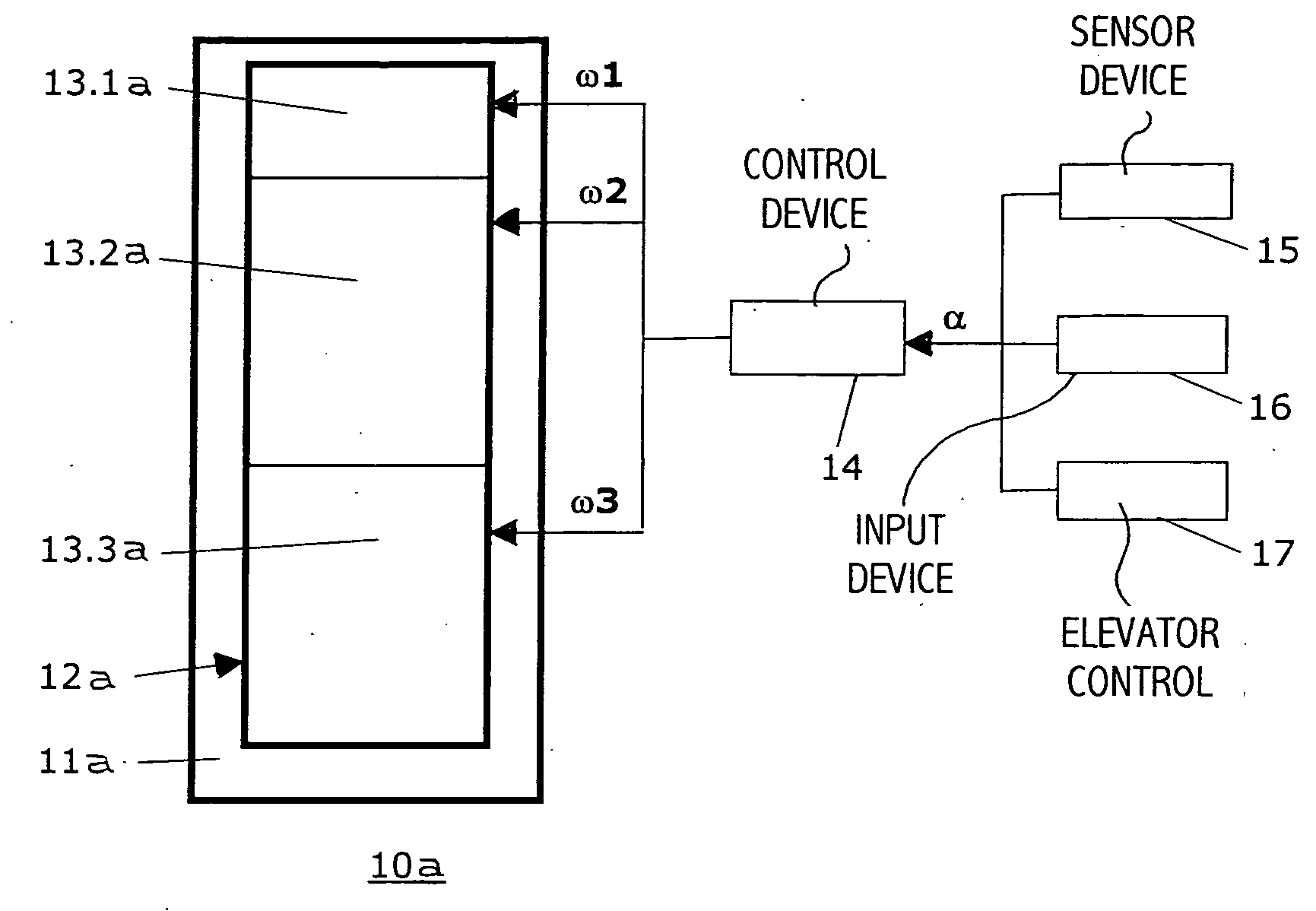
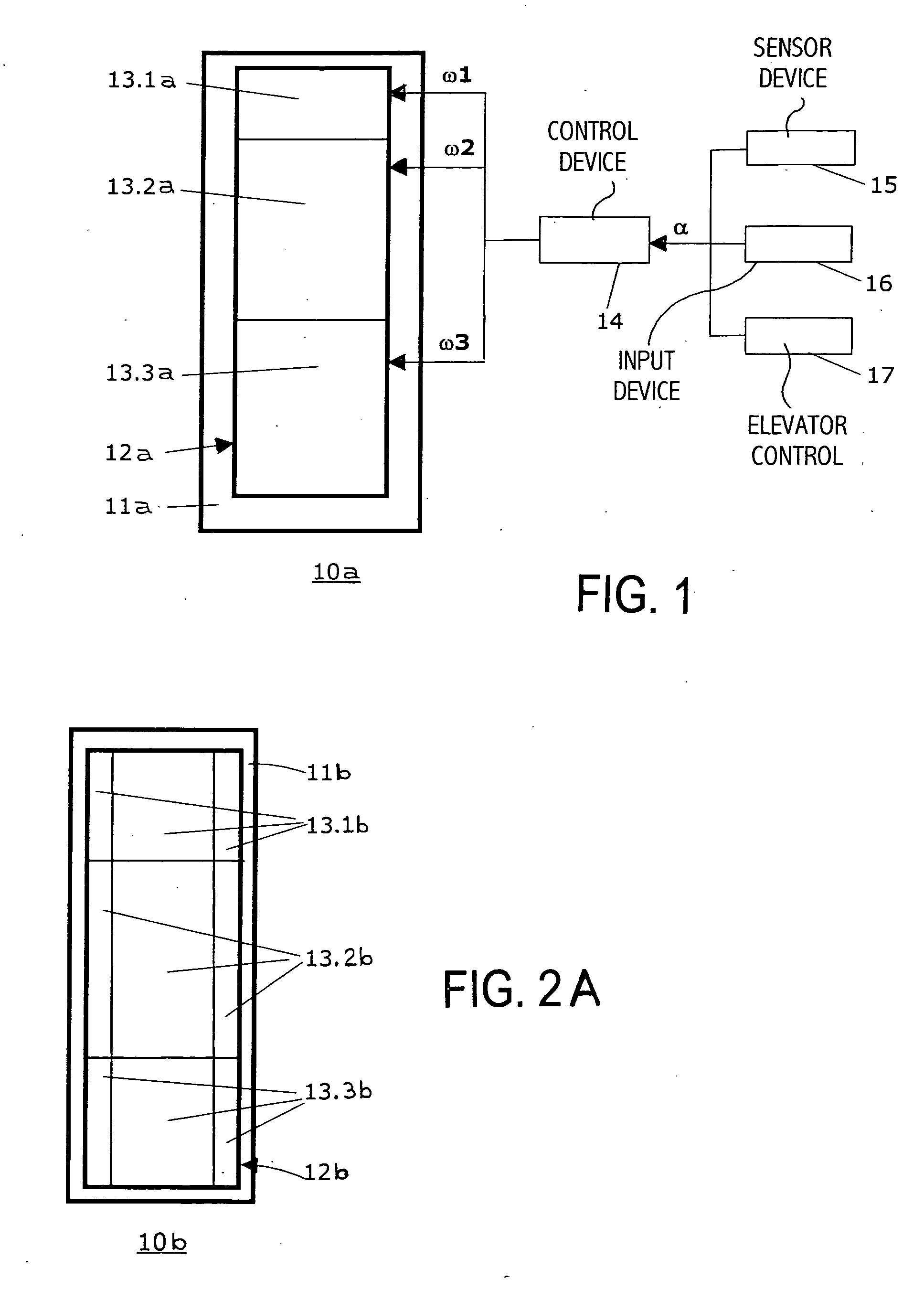
[0036]FIG. 1 shows a first embodiment wall plate 10a according to the present invention for an elevator installation, which can be used for mounting not only at an elevator shaft, but also at an elevator car. The wall plate 10a comprises a frame 11a extending about and retaining an edge of a glass part 12a. The glass part 12a is divided into three segments 13.1a, 13.2a and 13.3a. A control device 14, which is illustrated only schematically, serves the purpose of linking physical magnitudes ω1, ω2, ω3, the function of which is influencing the transparency of the segments 13.1a, 13.2a and 13.3a respectively, with a state information a on the basis of which the transparency of the segments 13.1a, 13.2a and 13.3a is to be set. The state information a can contain several items of information, wherein the state information α or the items of information can be ascertained by way of a sensor device 15, input by way of an input device 16, or input by way of an (digital) interface (not shown)...

second embodiment

[0037] A second embodiment wall plate 10b according to the present invention is illustrated in FIG. 2A for an elevator installation and comprises a frame 11b retaining a glass part 12b. The glass part 12a is divided into nine rectangular segments 13, the transparency of which is individually controllable. As shown, three rows of segments 13.1b, 13.2b and 13.3b are subdivided into wider central segments positioned between two narrower side segments.

third embodiment

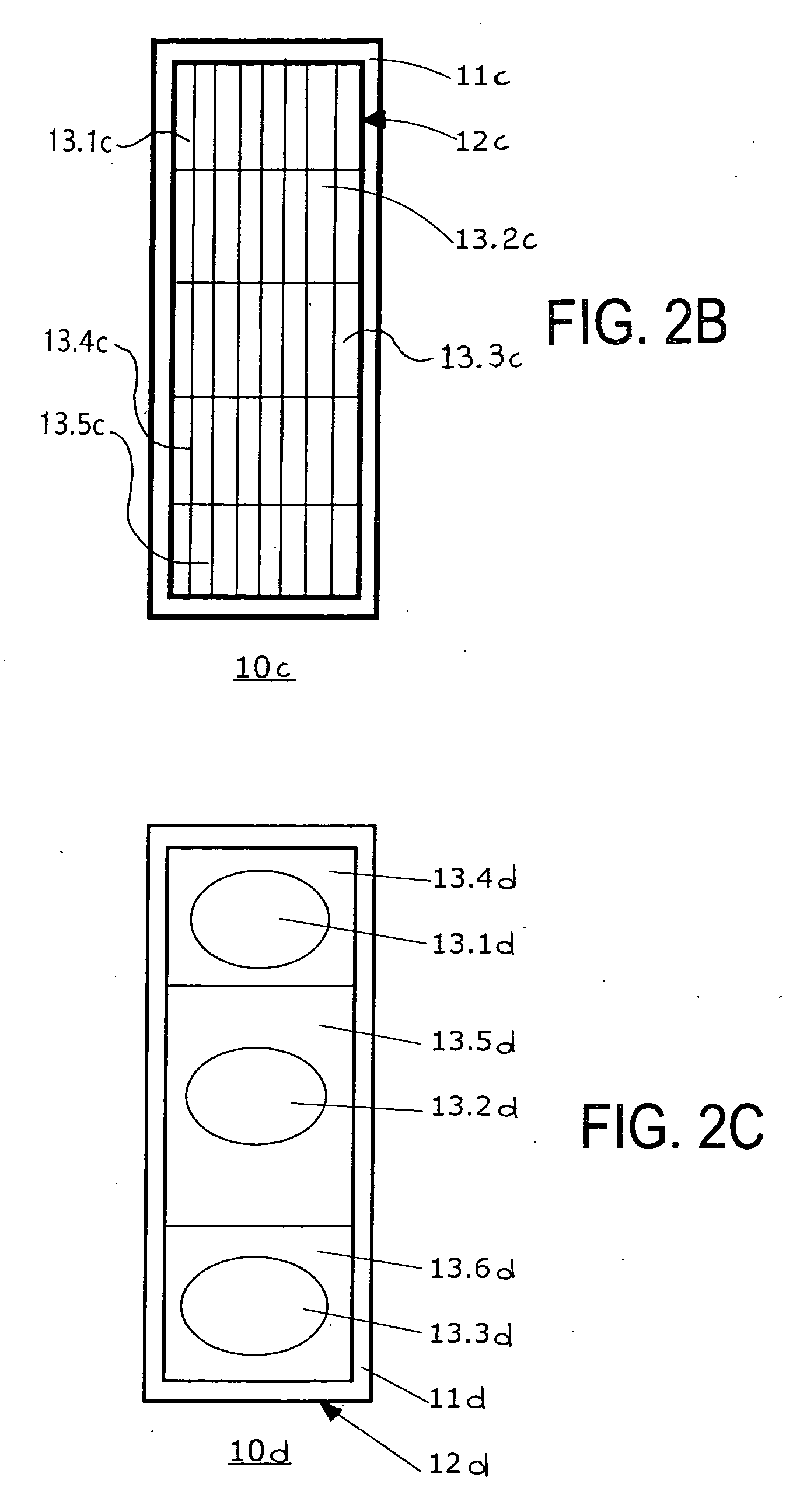
[0038]FIG. 2B shows a third embodiment wall plate 10c according to the present invention for an elevator installation, similarly with a frame 11c and a glass part 12c, wherein the glass part 12c is divided into forty rectangular segments 13.1c, 13.2c, 13.3c, 13.4c and 13.5c in five rows of eight segments each. These segments are smaller than the segments of the glass part 12b shown in FIG. 2A. The fine subdivision of the glass part 12c into numerous segments makes it possible to visualize, with the help of different levels of transparency, images or text in the form of a rastered image.


PUM


Abstract

A wall plate for use in an elevator installation has a glass part divided into segments, the transparency of which is individually controllable with physical magnitude information signals. A control device is connected to the segments for controlling the transparency on the basis of qualitative and quantitative state information and by linking the state information with the controlling magnitude information signals.

Description

BACKGROUND OF THE INVENTION [0001] The present invention relates to a wall plate with a glass part for an elevator installation and to an elevator installation with such a wall plate. [0002] By the term wall plate for an elevator installation there is to be understood, within the scope of the present description, plates for different boundaries of elevator shafts and elevator cars, thus not only plates for side walls, but also for floors, ceilings, doors or door panels, and windows. The components denoted as wall plates in that case do not have to be geometrically exact, but only approximately plate-shaped. [0003] Wall plates of elevator shafts and elevator cars in many cases have at least partial regions of glass or glass parts, wherein the glass can be fully transparent or opaque. [0004] Aesthetically appealing arrangements are achieved with, in particular, fully transparent glass and a contribution to user comfort can be made if a certain degree of looking out or looking in or lo...

Claims


Application Information

Patent Timeline
IPC IPC(8): B66B11/02G02F1/133G09F19/22
CPCB66B11/0226G09F19/22G02F1/13306
Inventor MEHR, DIETER
Owner INVENTIO AG
Why Eureka
Try Eureka