Current-conducting plate with electricity taken from bottom, track lamp and production method of current-conducting plate

A technology of conductive plates and tracks, applied in the direction of electrical components, printed circuits, circuit layout, etc., can solve the problems of short circuit, affecting the light source and iron plate magnetism, etc., and achieve the effect of reducing resistance, simple structure, and enhanced magnetic force

Pending Publication Date: 2021-03-19
深圳市卓越华予电路有限公司
View PDF0 Cites 1 Cited by
  • Summary
  • Abstract
  • Description
  • Claims
  • Application Information

AI Technical Summary

Problems solved by technology

[0005] The purpose of the present invention is: for the insulating highland barley paper existing in the prior art is not fixedly connected with the conductive strip or the iron plate, the displacement of the insulating highland barley paper may be caused during manual installation, so that a path is formed between the iron plate and the double-sided conductive PCB board , the problem of short circuit during use, and the PCB board between the iron plate and the track light will affect the magnetic force between the light source and the iron plate, providing a conductive plate for taking electricity from the bottom

Method used


Image

  • Current-conducting plate with electricity taken from bottom, track lamp and production method of current-conducting plate
  • Current-conducting plate with electricity taken from bottom, track lamp and production method of current-conducting plate
  • Current-conducting plate with electricity taken from bottom, track lamp and production method of current-conducting plate

Examples


Embodiment 1

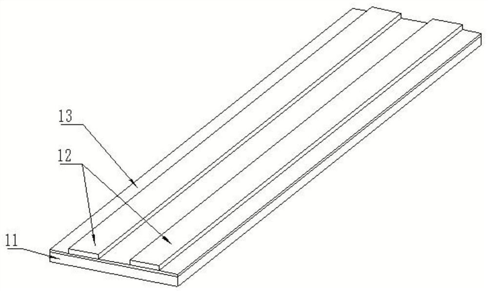
[0048] Such as figure 1The shown conductive plate 1 for taking electricity from the bottom includes a substrate 11 and a conductive strip 12 made of magnetic materials. The substrate 11 can be an iron plate, or other plates that can generate magnetic attraction with a magnet. The upper surface of the substrate 11 is one side, and the lower surface is the other side. When installing the conductive plate 1, the direction of inserting it into the track is the length direction of the substrate 11; the material of the conductive strip 12 is copper or copper alloy. The thickness of the conductive strips 12 is 0.035-0.35mm, the number of the conductive strips 12 can be two or three and there is a gap between two adjacent conductive strips 12, the number of the conductive strips 12 on each side is It is determined according to whether the light source 5 uses direct current or alternating current. A first insulating layer 13 with a thickness of 0.15-0.3 mm is bonded between the substr...

Embodiment 2

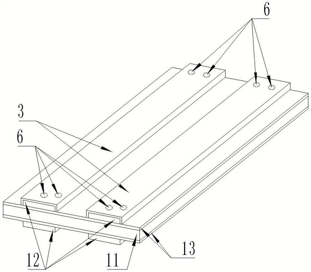
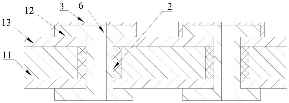
[0050] Such as figure 2 and image 3 A conductive plate 1 that takes power from the bottom is shown, and only part of its length is shown in the figure, including a substrate 11 made of magnetic material, a first insulating layer 13 and a conductive strip 12. The substrate 11 can be an iron plate, Also can be other plates that can generate magnetic attraction with magnets, the upper surface of the substrate 11 is one side, and the lower surface is the other side; The first insulating layer 13 can be a prepreg with a thickness of 0.15-0.3mm, the first insulating layer 13 is bonded to the upper and lower surfaces of the substrate 11 by pressing, and the conductive strip 12 is made of copper or copper alloy material , the conductive strips 12 are bonded to the surface of the first insulating layer 13 on the upper and lower surfaces of the substrate 11 by pressing and extend along the length direction of the substrate 11; the number of conductive strips 12 on the upper and lower...

Embodiment 3

[0052] A track 4 light such as Figure 4 As shown, it includes a light source 5 connected to a plurality of rails 4. The figure only shows the situation that two rails 4 are connected. The lower part of the inner surface is slidably connected with the conductive plate 1 for taking electricity from the bottom provided by the technical solution in embodiment 2, and the conductive surface of the conductive plate 1 faces upward; The chute 7, the light source 5 slides in the chute 7; the conductive strip 12 on the conductive plate 1 is electrically connected with the light source 5 and provides power for the normal operation of the light source 5; a magnet is arranged in the light source 5, and the magnet The substrate of the conductive plate 1 generates magnetic force and attracts each other, and the magnetic force makes the light source 5 contact with the conductive plate 1 and maintain good electrical connection; the front and rear ends of the pad surface of the conductive plate...


PUM

PropertyMeasurementUnit
thicknessaaaaaaaaaa
thicknessaaaaaaaaaa
thicknessaaaaaaaaaa

Abstract

The invention relates to the field of lighting equipment, in particular to a current-conducting plate. The current-conducting plate comprises a base plate and two or three conductive strips, the baseplate is a magnetic material component, the conductive strips extend in the length direction of the base plate, a gap is formed between every two adjacent conductive strips, a first insulating layer is bonded to one side of the base plate, the conductive strips are bonded to one side, back to the base plate, of the first insulating layer, and the thickness of the first insulating layer is 0.15-0.3mm. By adopting the current-conducting plate provided by the invention, the problem of short circuit in use due to insulation failure caused by displacement of the first insulating layer is eliminated. The current-conducting plate with electricity taken from the bottom is used for supplying power to a light source, and the distance between the light source and the base plate is only the thicknessof the first insulating layer, namely 0.15-0.3 mm, and is far smaller than the distance between a light source and a base plate in the prior art, so that the magnetic force between the light source and the base plate is enhanced, and the adsorption effect of the base plate on the light source is enhanced.

Description

technical field [0001] The invention relates to the technical field of lighting equipment, in particular to a conductive plate for taking power from the bottom, a track lamp and a production method for the conductive plate. Background technique [0002] At present, the electromagnetic suction track at the bottom usually adopts the combination of iron plate and PCB circuit board. The PCB circuit board transmits power to the light source. There is an iron plate under the PCB circuit board. An insulating highland barley paper is arranged between the PCB board and the iron plate. A magnet is arranged on the light source to prevent the light source from detaching from the track. [0003] Currently used PCB circuit boards can be divided into single-sided conductive PCB boards and double-sided conductive PCB circuit boards. When using a single-sided conductive PCB circuit board as a conductive carrier, the rails need to be connected with rail connectors to ensure electrical commun...

Claims


Application Information

Patent Timeline
Patent Type & Authority Applications(China)
IPC IPC(8): F21V23/06H05K1/09H05K3/00
CPCF21V23/06H05K1/09H05K3/0044H05K3/0002
Inventor 刘洪
Owner 深圳市卓越华予电路有限公司
Why Eureka
Try Eureka