Spray bottle

a spray bottle and bottle body technology, applied in the field of spray bottles, can solve the problems and achieve the effect of prolonging the useful life of a given spray bottl

Inactive Publication Date: 2005-04-28
SILVAGGIO JOSEPH A
View PDF5 Cites 9 Cited by
  • Summary
  • Abstract
  • Description
  • Claims
  • Application Information

AI Technical Summary

Benefits of technology

[0004] The present invention pertains to modifying an existing spray bottle by including a baffle in a lower portion of the spray bottle which will create a reservoir or well in the bottle when the bottle is held in a horizontal position. Having the d...

Problems solved by technology

Having the dip or siphon tube of the spray mechanism positioned in the well or secondary reservoir in the bottle will enable the us...

Method used


Image

  • Spray bottle
  • Spray bottle
  • Spray bottle

Examples


Embodiment Construction

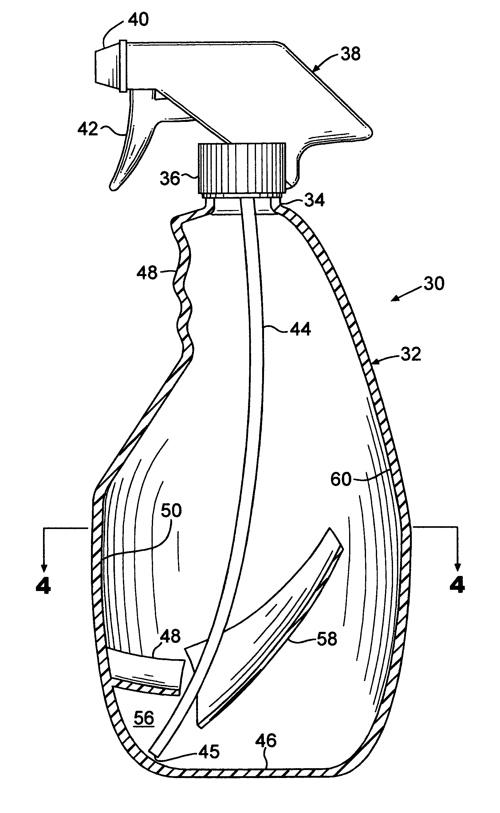
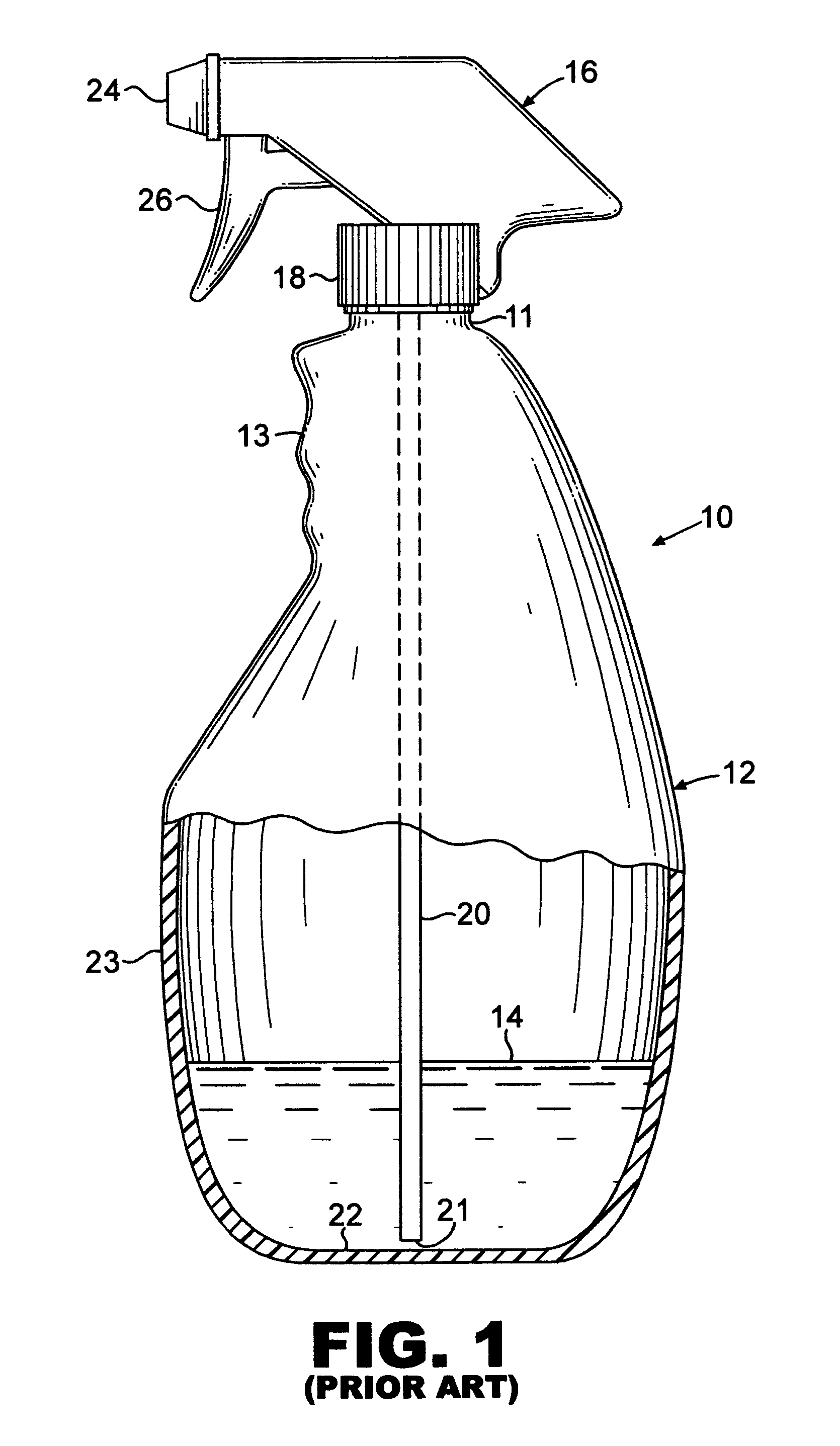
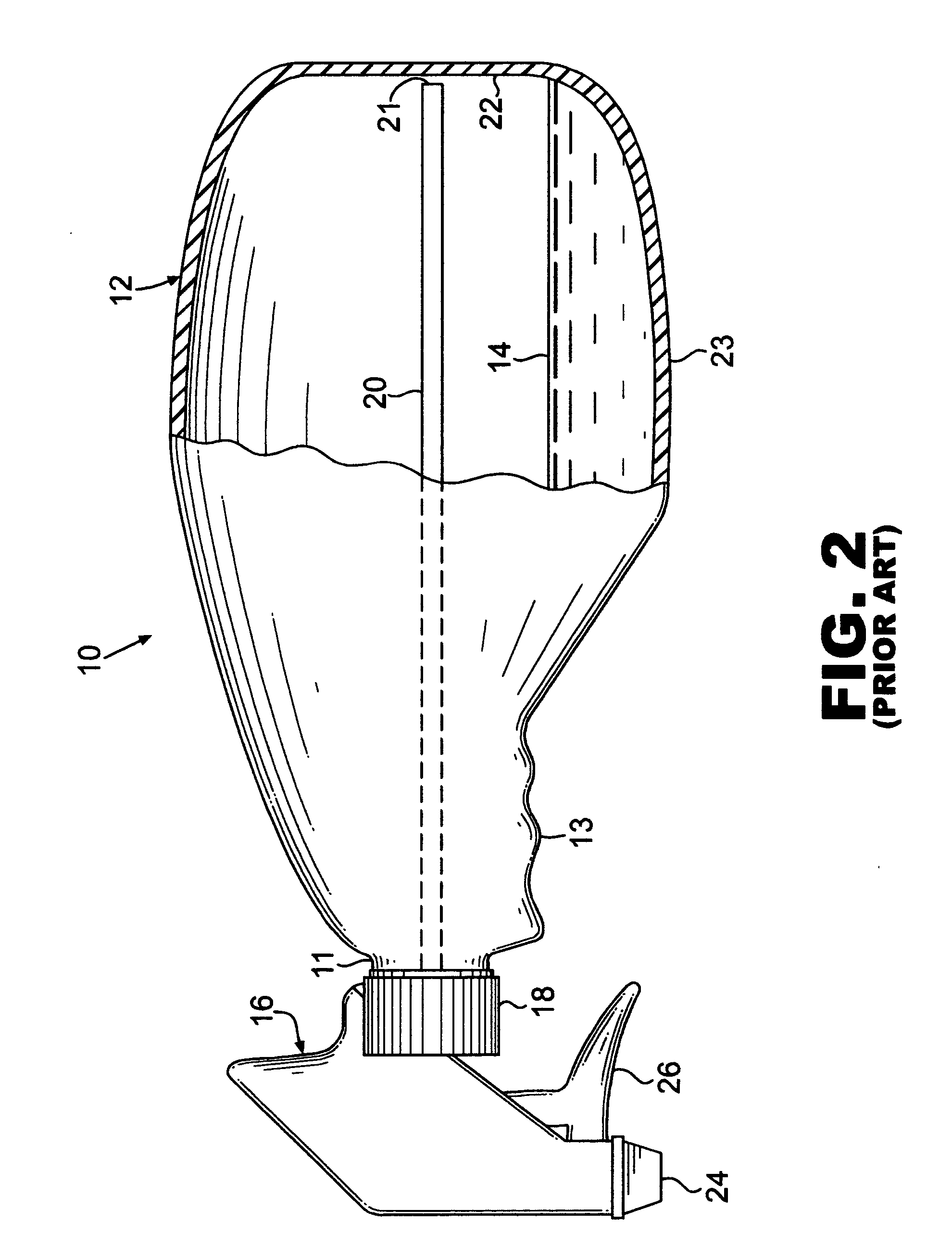
[0013] A spray bottle shown generally as 10 in FIGS. 1 and 2 according to the prior art comprises a bottle or reservoir portion 12 which will hold a fluid 14 to be dispensed from the bottle 12 by a spray or pump mechanism 16 which usually is included in a cap 18 closing the neck portion 11 of the bottle 12. Bottle 12 can be made in any convenient shape such as shown in FIG. 1 wherein an upper portion 13 of bottle 12 has the general shape of a pistol grip. The spray mechanism 16 includes a dip or siphon tube 20 that extends toward the bottom 22 of the bottle 12 so that the fluid 14 inside the bottle 12 can be pumped, by activating trigger 26, through the siphon tube 20 to a spray nozzle 24 for dispensing. In prior art bottles the siphon tube is generally vertical and extends to a location proximate the bottom 22 of the spray bottle 12 as shown in FIG. 1. When the spray bottle 12 is held in a vertical position almost all of the liquid can be dispensed using the spray mechanism 16. How...


PUM


Abstract

A hand held bottle for dispensing fluids in a spray having a reservoir for holding fluid and a dispensing mechanism including a siphon tube disposed in the fluid, a first baffle positioned in the bottle to create a well or accumulation of fluid in a bottom portion of the bottle when it is moved from a vertical to a horizontal position, especially when the total level of fluid in the reservoir is low. A second baffle positions the siphon tube within the well.

Description

BACKGROUND OF THE INVENTION [0001] The present invention pertains to spray bottles and in particular, to those spray bottles used to dispense, inter alia, common household cleaning fluids. Spray bottles find numerous uses both domestically and industrially for dispensing a variety of fluids from plain liquids, e.g. water, alcohol, to complex liquid based compounds. [0002] Spray bottles are commonly used in restaurants to dispense a cleaning fluid to clean tables in between uses by successive patrons. [0003] The problem with prior art spray bottles is that when the bottle is held in a horizontal position and there is only a small amount of fluid left in the bottle, the siphoning tube is not immersed into the fluid and the bottle can no longer spray the contents. Thus, with prior art spray bottles there is always fluid left in the bottle that can not be extracted by the normal spray mechanism. At that point the user must either refill the bottle or transfer the contents from one spray...

Claims


Application Information

Patent Timeline
IPC IPC(8): B05B11/00
CPCB05B11/0059B05B15/005B05B11/0037B05B11/3057B05B15/30B05B11/1057
Inventor SILVAGGIO, JOSEPH A.
Owner SILVAGGIO JOSEPH A
Why Eureka
Try Eureka