Video signal processor
- Summary
- Abstract
- Description
- Claims
- Application Information
AI Technical Summary
Benefits of technology
Problems solved by technology
Method used
Image
Examples
first embodiment
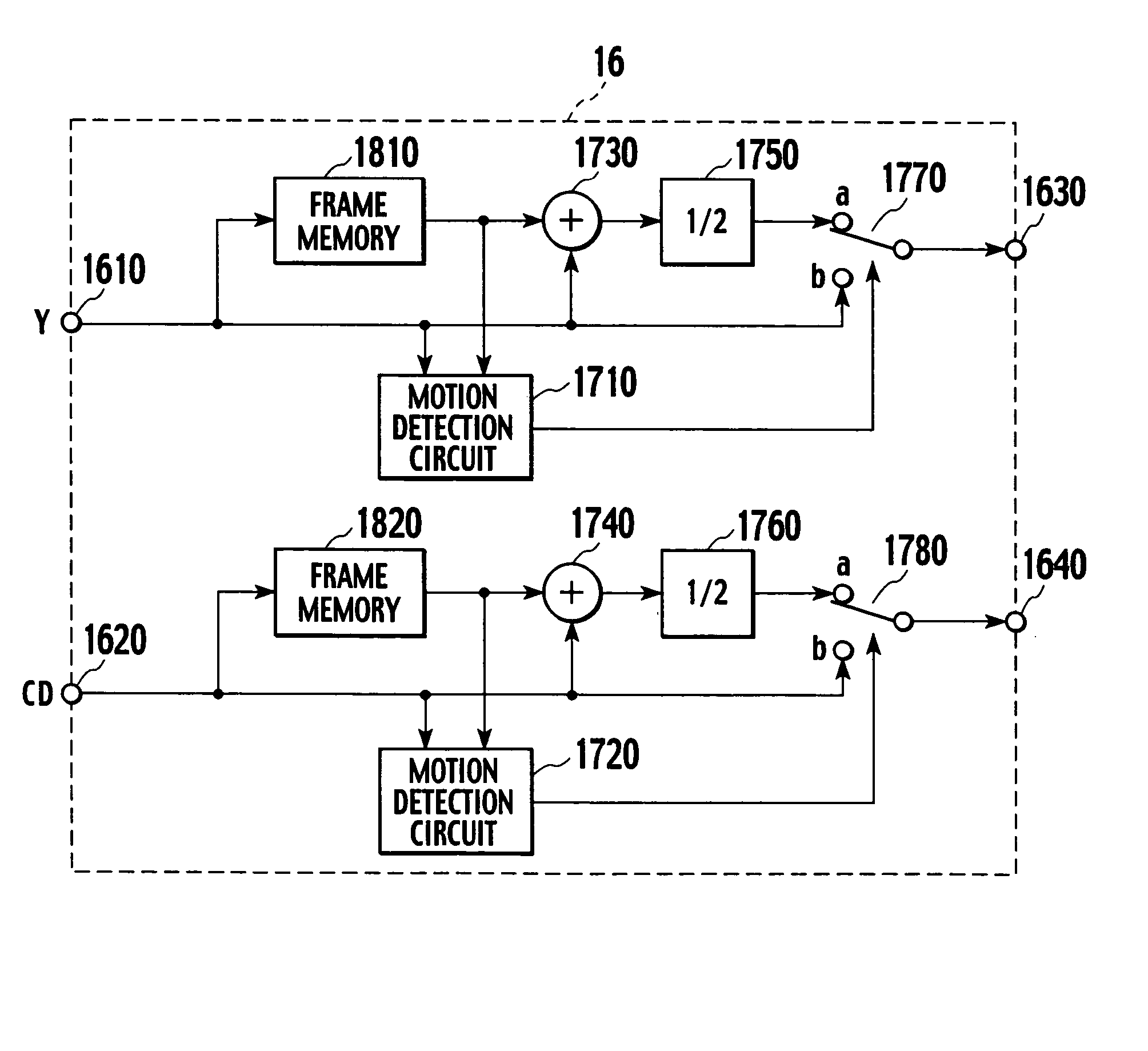
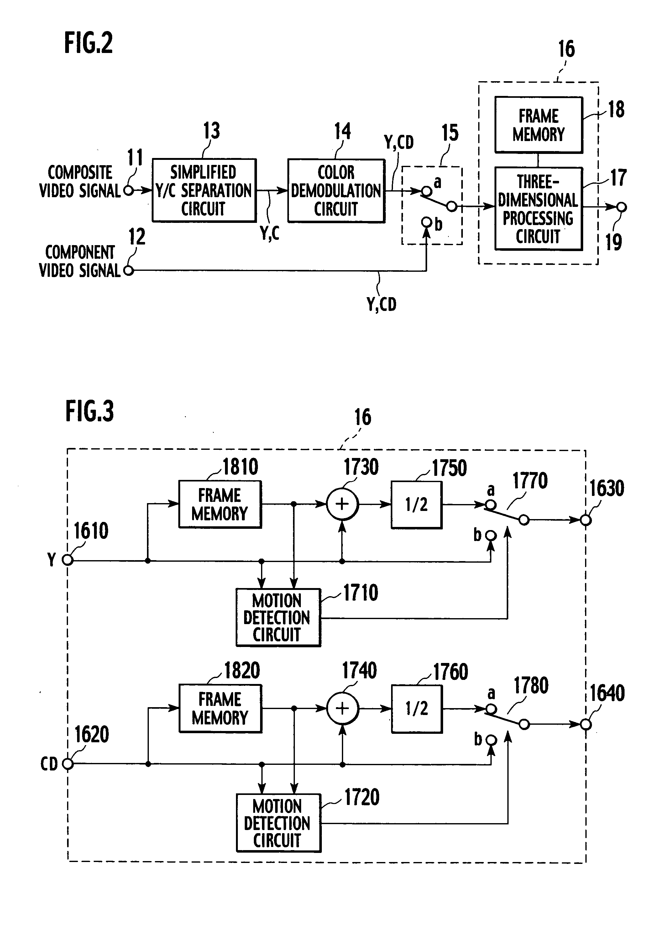
[0040]FIG. 2 is a block diagram showing a first embodiment of a video signal processor according to the present invention. FIG. 3 is a block diagram showing a concrete structural example of a three-dimensional processing portion 16 depicted in FIG. 2.
[0041] In FIG. 2, a composite video signal is input to an input terminal 11, and a component video signal is input to an input terminal 12. The composite video signal is input to a simplified Y / C separation circuit 13. The simplified Y / C separation circuit 13 is a Y / C separation circuit which does not include a frame memory (which does not perform three-dimensional processing), and it is, e.g., a band pass filter which extracts a chrominance subcarrier frequency (3.58 MHz in case of the NTSC mode) as a central band, a comb type filter using a line correlation, or a two-dimensional Y / C separation circuit. The simplified Y / C separation circuit 13 separates a Y signal and a C signal from each other in a simplified manner. The Y signal and...
second embodiment
[0051]FIG. 4 is a block diagram showing a second embodiment of the video signal processor according to the present invention. FIG. 5 is a block diagram showing a concrete structural example of a three-dimensional processing portion 16′ in FIG. 4.
[0052] In the second embodiment shown in FIGS. 4 and 5, like reference numerals denote parts equal to those in the first embodiment shown in FIGS. 2 and 3, and the explanation thereof will be appropriately eliminated. As shown in FIG. 4, the second embodiment is characterized in that the C signal separated by the simplified Y / C separation circuit 13 is input to the three-dimensional processing portion 16′ in order to further improve the image quality of the Y signal. Specifically, as shown in FIG. 5, the C signal output from the simplified Y / C separation circuit 13 is input to an input terminal 1650, and a mixer 1790 mixes the Y signal input to the input terminal 1610 with the C signal input to an input terminal 1650, and supplies a result ...
third embodiment
[0054]FIG. 6 is a block diagram showing a third embodiment of the video signal processor according to the present invention.
[0055] Although the first and second embodiments mentioned above perform the three-dimensional processing by using the three-dimensional processing portion 16 even if a processing target is the component video signal, the third embodiment shown in FIG. 6 is configured not to perform the three-dimensional processing with respect to the component video signal which does not include a dot interference component or a cross-color interference component. It is preferable to switch the processing in such a manner that the three-dimensional processing is performed with respect to the component video signal which may possibly include a dot interference component or a cross-color interference component as described above but the three-dimensional processing is not carried out with respect to the component video signal which is considered not to include the dot interfere...
PUM
 Abstract
Description
Claims
Application Information
 - R&D
- Intellectual Property
- Life Sciences
- Materials
- Tech Scout
- Unparalleled Data Quality
- Higher Quality Content
- 60% Fewer Hallucinations
Browse by: Latest US Patents, China's latest patents, Technical Efficacy Thesaurus, Application Domain, Technology Topic, Popular Technical Reports.
© 2025 PatSnap. All rights reserved.Legal|Privacy policy|Modern Slavery Act Transparency Statement|Sitemap|About US| Contact US: help@patsnap.com


