Speaker cabinet with increased air circulation efficiency

a technology of air circulation efficiency and speaker cabinet, which is applied in the direction of electrical transducer details, cabinet/cabinet/drawer, electric apparatus casing/cabinet/drawer, etc., can solve the problems of adversely affecting the vibration of the diaphragm, prior design suffered a disadvantage, and interfere with low-frequency sounds, etc., to facilitate air circulation, increase the ratio of an opening to an area of the rear, and strengthen the low-frequency resonance of the cabin

Active Publication Date: 2005-04-28
WANG CHAO LANG
View PDF6 Cites 17 Cited by
  • Summary
  • Abstract
  • Description
  • Claims
  • Application Information

AI Technical Summary

Benefits of technology

[0006] One object of the present invention is to provide a speaker cabinet comprising a hollow case in which a top and a bottom thereof both are wavily tapered from a pair of opposite edges of a front opening to a rear thereof. By utilizing the wavy, rearward taper design of the top and the bottom, a ratio of an area of the opening to an area of the rear is increased. Thus, air inside the case will be compressed rearward when a diaphragm of a woofer vibrates. Next, the compressed air will quickly flow toward the rear along the wavy, rearward taper inner surfaces of the top and the bottom. As a result, air dynamic at the rear is higher and stronger low-frequency resonance of the cabinet can be generated. Moreover, air may flow back to the opening when it hits the rear. Advantageously, most air will flow back from the rear to at least one low-frequency sounds reflection channel on the cover along the wavy, rearward taper inner surfaces of the top and the bottom prior to exit. This can facilitate air circulation through the case and significantly reduce a probability of secondary reflection of sound wave.
[0007] Another object of the present invention is to provide a speaker cabinet in which two sides of the case are extended parallel from another pair of opposite edges of the opening to the rear. Two arcuate (or inclined) surfaces of the rear proximate the sides are formed integrally with the sides. By configuring a rearward taper shape of the rear, air inside the case will be compressed rearward when the diaphragm of the woofer vibrates. Further, the compressed air with high dynamic will flow quickly toward the rear to concentrate on the inner surface of the rear corresponding to the low-frequency sounds reflection channel. Thereafter, air flowed back from the rear toward the opening will be highly concentrated on the low-frequency sounds reflection channel prior to freely exiting therefrom. By utilizing the present invention, adverse effect on the vibration of the diaphragm of the woofer caused by the compressed air and vacuum suck effect inside the case will be substantially eliminated, and distortion in the low-frequency sounds is much improved.
[0008] Still another object of the present invention is to provide a speaker cabinet in which by utilizing the wavy, rearward taper shapes of the top and the bottom, air inside the case will be compressed rearward to concentrate on the inner surface of the rear corresponding to the rears of the low-frequency sounds reflection channel when the diaphragm of the woofer vibrates prior to exiting from the low-frequency sounds reflection channel. Alternatively, by utilizing the vacuum suck effect inside the case, outside air will be introduced into the case through the low-frequency sounds reflection channel. By utilizing the present invention, adverse effect on the vibration of the diaphragm of the woofer caused by the compressed air and vacuum suck effect inside the case will be substantially eliminated, and both quality and volume of low-frequency sounds output of the woofer are much increased.

Problems solved by technology

Otherwise, low-frequency sounds may be interfered.
This is not desired since it may adversely affect the vibration of the diaphragm 1201 of the woofer 120.
However, the prior design suffered a disadvantage.

Method used


Image

  • Speaker cabinet with increased air circulation efficiency
  • Speaker cabinet with increased air circulation efficiency
  • Speaker cabinet with increased air circulation efficiency

Examples


Embodiment Construction

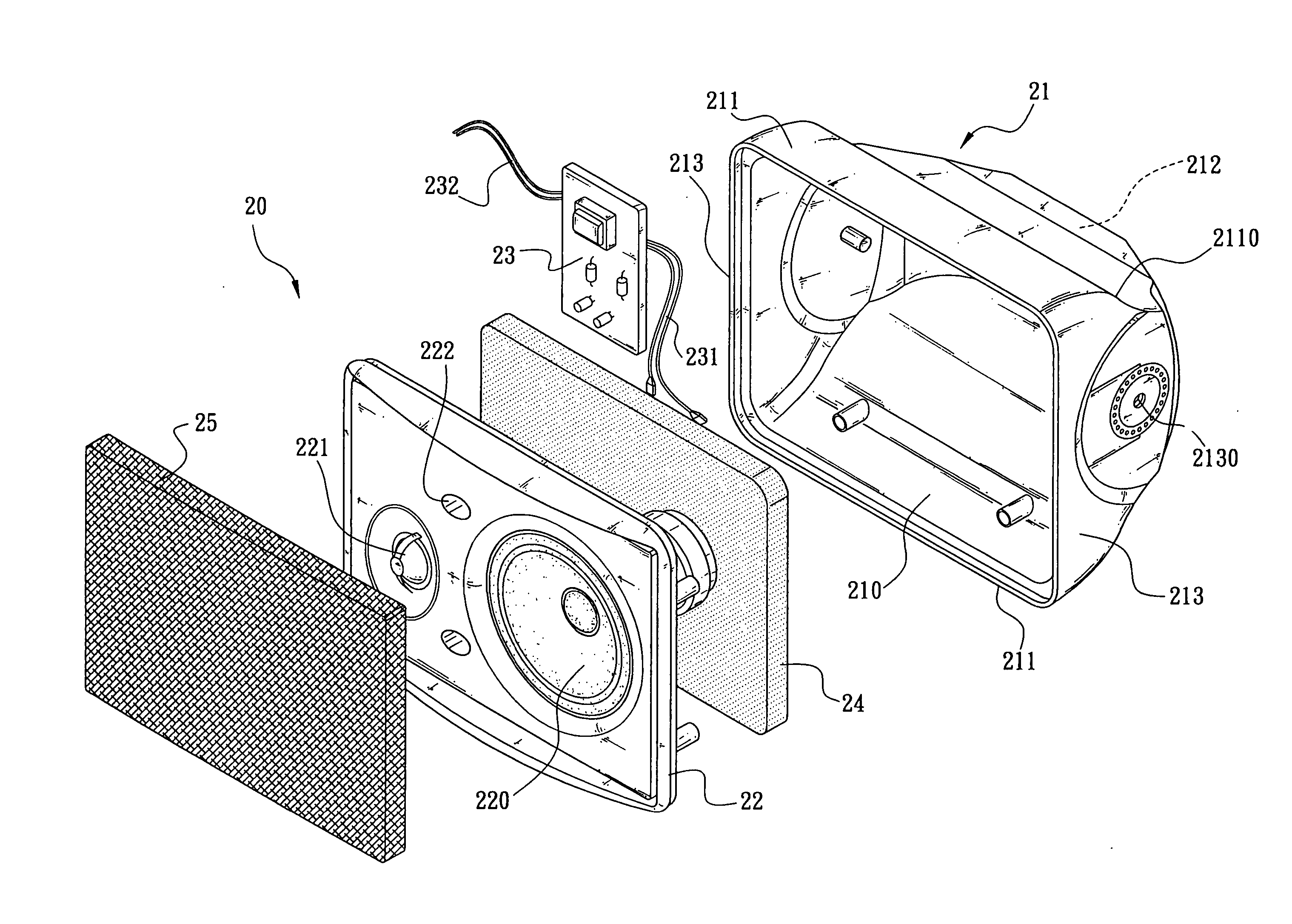
[0016] Referring to FIG. 4, there is shown a speaker cabinet 20 with increased air circulation efficiency in accordance with the invention. As shown, the speaker cabinet 20 comprises a hollow case 21 and a cover 22. The hollow case 21 comprises a front opening 210, a wavy top 211, a wavy bottom 211, and a rear 212 in which the top 211 and the bottom 211 are wavily tapered from a pair of opposite edges of the opening 210 to the rear 212. Two sides 213 of the hollow case 21 are also extended parallel from another pair of opposite edges of the opening 210 to the rear 212. In other words, the area of the rear 212 is smaller than that of the opening 210. A pivot hole 2130 is provided at either side 213 proximate the rear 212. A bracket (not shown) can be provided at the pivot holes 2130 for fastening the hollow case 21 at a predetermined place. A sound control circuit 23 is provided on the inner surface of the rear 212 within the hollow case 21. The sound control circuit 23 is used to re...


PUM


Abstract

The present invention is to provide a speaker cabinet comprising a hollow case in which a top and a bottom thereof both are wavily tapered from a pair of opposite edges of a front opening to a rear thereof. By utilizing the wavy, rearward taper design of the top and the bottom, a ratio of an area of the opening to an area of the rear is increased. Thus, air inside the case will be compressed rearward when a diaphragm of a woofer vibrates. Next, the compressed air will quickly flow toward the rear along the wavy, rearward taper inner surfaces of the top and the bottom. As a result, air dynamic at the rear is higher and stronger low-frequency resonance of the cabinet can be generated.

Description

FIELD OF THE INVENTION [0001] The present invention relates to speaker construction and more particularly to an improved speaker cabinet with increased air circulation efficiency. BACKGROUND OF THE INVENTION [0002] A conventional speaker cabinet 10 is illustrated in FIG. 1. As shown, the speaker cabinet 10 comprises a substantially parallelepiped, hollow case 11 and a cover 12. The hollow case 11 comprises a front opening 110, a top 111, a bottom 111, and a rear 112 in which the top 111 and the bottom 111 are obliquely tapered from a pair of opposite edges of the opening 110 to the rear 112. Two sides 113 of the hollow case 11 are also extended parallel from another pair of opposite edges of the opening 110 to the rear 112. A U-shaped bracket 16 is pivotal about the sides 113 proximate the rear 112. The U-shaped bracket 16 is used to fasten at a predetermined place. A sound control circuit 13 is provided on the inner surface of the rear 112 within the hollow case 11. The sound contr...

Claims


Application Information

Patent Timeline
Patent Type & Authority Applications(United States)
IPC IPC(8): H04R1/02H04R1/20H04R1/28
CPCH04R1/288
Inventor WANG, CHAO-LANG
Owner WANG CHAO LANG
Why Eureka
Try Eureka