Method for predicted reactor simulation

a technology for reactors and simulation methods, applied in the direction of nuclear elements, instruments, greenhouse gas reduction, etc., can solve the problems of complex and computation-intensive optimization problems that can be very time-consuming to solve, and the small percentage of configurations that satisfy all the applicable design constraints economically feasibl

Active Publication Date: 2005-04-28
GLOBAL NUCLEAR FUEL -- AMERICAS
View PDF8 Cites 52 Cited by
  • Summary
  • Abstract
  • Description
  • Claims
  • Application Information

AI Technical Summary

Problems solved by technology

Due to the vast number of possible different operational values and combinations of values that these independent control-variables can assume, it is a formidable challenge and a very time consuming task, even using known computer-aided methodologies, to attempt to analyze and optimize all the individual influences on core reactivity and performance.
In addition, only a small percentage of the configurations that satisfy all the applicable design constraints are economically feasible.
However, such arrangements are not always possible to achieve while still satisfying plant specific design constraints.
Since each fuel bundle can be loaded at a variety of different locations relative to other bundles, identifying a core loading arrangement that produces optimum performance of the core for each fuel-cycle presents a complex and computation-intensive optimization problem that can be very time consuming to solve.
Since it is desirable to maximize the core-cycle energy in order to minimize nuclear fuel cycle costs, developing an optimum control blade positioning strategy presents another formidable independent control-variable optimization problem that must also be taken into consideration when attempting to optimize fuel-cycle design and management strategies.
Due to circumstances that require a rapid response to changing plant operating conditions, a core design engineer may be faced with the formidable challenge of specifying values for over 200 independent control-variables within a very short time frame.
Moreover, using this trial-and-error approach, once a fuel-cycle design arrangement that satisfies all design and safety constraints has been identified, it may turn out that the identified arrangement may not provide the actual maximum cycle-energy.
Such an actual optimum core arrangement, however, may not necessarily be identified through the above described trial and error process.

Method used


Image

  • Method for predicted reactor simulation
  • Method for predicted reactor simulation
  • Method for predicted reactor simulation

Examples


Embodiment Construction

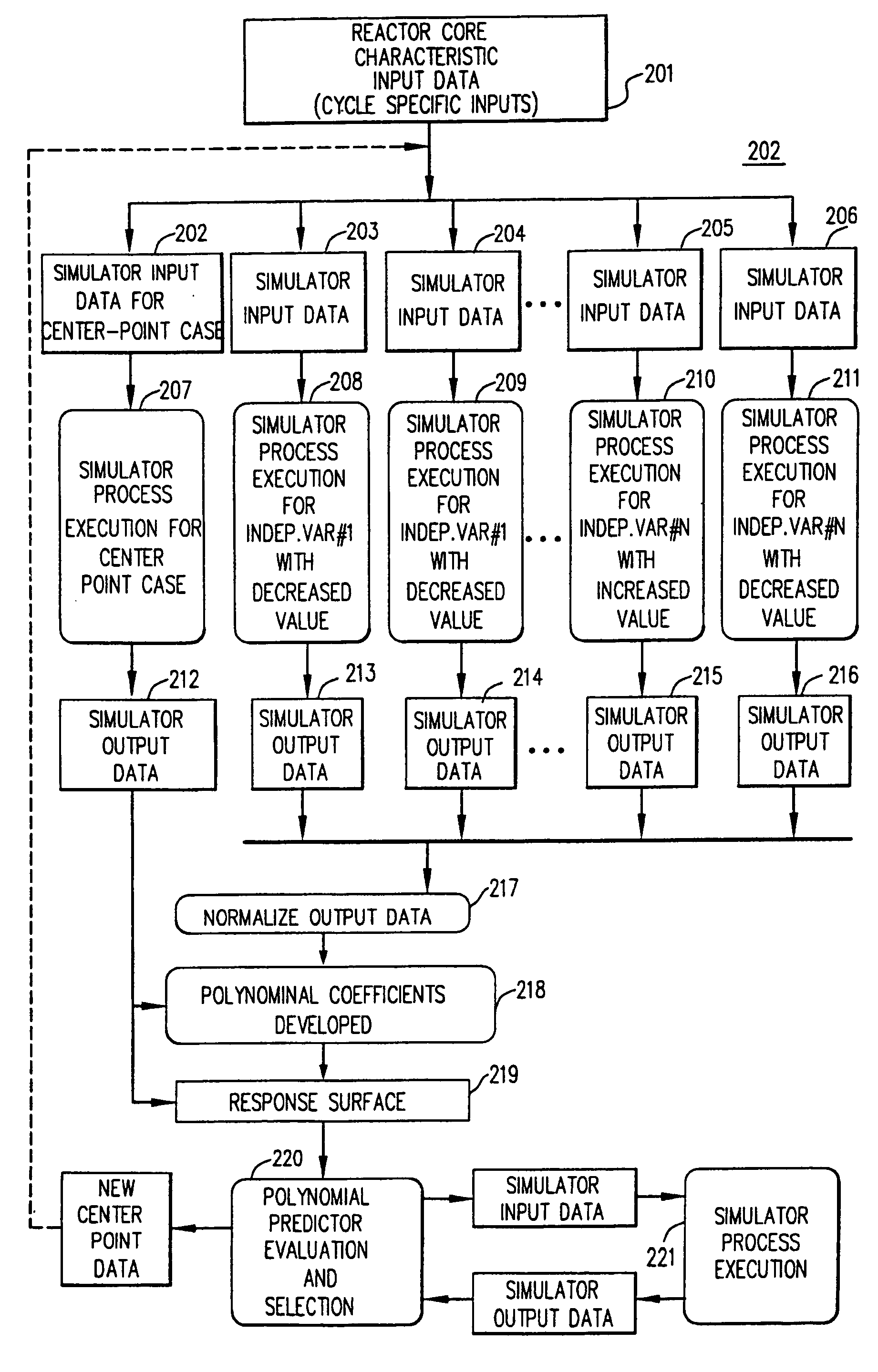
[0028] The present invention uses a response surface as a type of cyber-workspace, and allows for real-time predicted reactor simulations. A response surface defines the relationships between a number of design inputs and an number of operation outputs for one or more aspects of reactor core design. Accordingly, prior to describing the present invention, a detailed description of creating the response surface is provided in the context of a method of optimizing a reactor core design using the response surface. Subsequently, the method for predicted reactor core simulation will be provided.

Creating a Response Surface

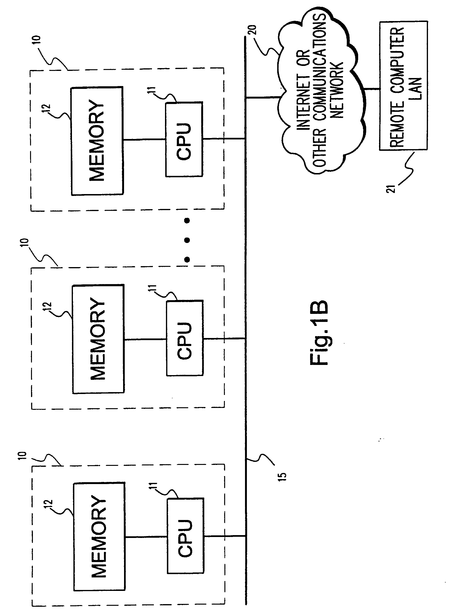
[0029] The following description is directed toward an exemplary embodiment for creating a response surface. The methodology for creating the response surface may be operative as an end-user application running, for example, under the Microsoffe Windows 95 / NT environment. However, creation of the response surface is not limited to any particular computer system or any ...


PUM


Abstract

In the method for reactor simulation, a user modifies one or more design inputs used in creating a response surface. The response surface defines relationships between the design inputs and operational outputs of at least one or more aspects of a core design. A reactor simulation is then generated based on the response surface for the core design and the modified design input.

Description

BACKGROUND OF THE INVENTION [0001] A nuclear reactor core includes many individual components that have different characteristics that may affect a strategy for efficient operation of the core. For example, a nuclear reactor core has many, e.g., several hundred, individual fuel assemblies (bundles) that have different characteristics and which must be arranged within the reactor core or “loaded” so that the interaction between fuel bundles satisfies all regulatory and reactor design constraints, including governmental and customer specified constraints. Similarly, other controllable elements and factors that affect the reactivity and overall efficiency of a reactor core must also be taken into consideration if one is to design or develop an effective control strategy for optimizing the performance of a reactor core at a particular reactor plant. Such “operational controls” (also referred to interchangeably herein as “independent control-variables” and “design inputs”) include, for e...

Claims


Application Information

Patent Timeline
Patent Type & Authority Applications(United States)
IPC IPC(8): G21D3/00G21C17/00G21D3/08
CPCG21D3/001G21D3/08G21Y2002/201Y02E30/40G21Y2002/304G21Y2004/40G21Y2002/202Y02E30/00Y02E30/30
Inventor RUSSELL, WILLIAM EARL IIKROPACZEK, DAVID JOSEPH
Owner GLOBAL NUCLEAR FUEL -- AMERICAS
Why Eureka
Try Eureka