Digital signal encoding method, decoding method, encoding device, decoding device, digital signal encoding program, and decoding program

a digital signal and signal technology, applied in the field of digital signal encoding methods, decoding methods, digital signal encoding programs, and decoding programs, can solve problems such as problems such as the degradation of reproduced signals

Active Publication Date: 2005-04-28
NIPPON TELEGRAPH & TELEPHONE CORP
View PDF1 Cites 198 Cited by
  • Summary
  • Abstract
  • Description
  • Claims
  • Application Information

AI Technical Summary

Benefits of technology

[0062]FIG. 25 illustrates an example of layer splitting of a code in accordance with a seventh embodiment of the present invention.
[0063]FIG. 26 illustrates the relationship of a combination of layer split codes, various sampling frequencies, and various amplitude resolutions.
[0064]FIG. 27 is a functional block diagram of an encoding apparatus in accordance with the seventh embodiment of the present inventio

Problems solved by technology

However, the distortion depends on encoding conditions and input signals, and the degr

Method used


Image

  • Digital signal encoding method, decoding method, encoding device, decoding device, digital signal encoding program, and decoding program
  • Digital signal encoding method, decoding method, encoding device, decoding device, digital signal encoding program, and decoding program
  • Digital signal encoding method, decoding method, encoding device, decoding device, digital signal encoding program, and decoding program

Examples


first embodiment

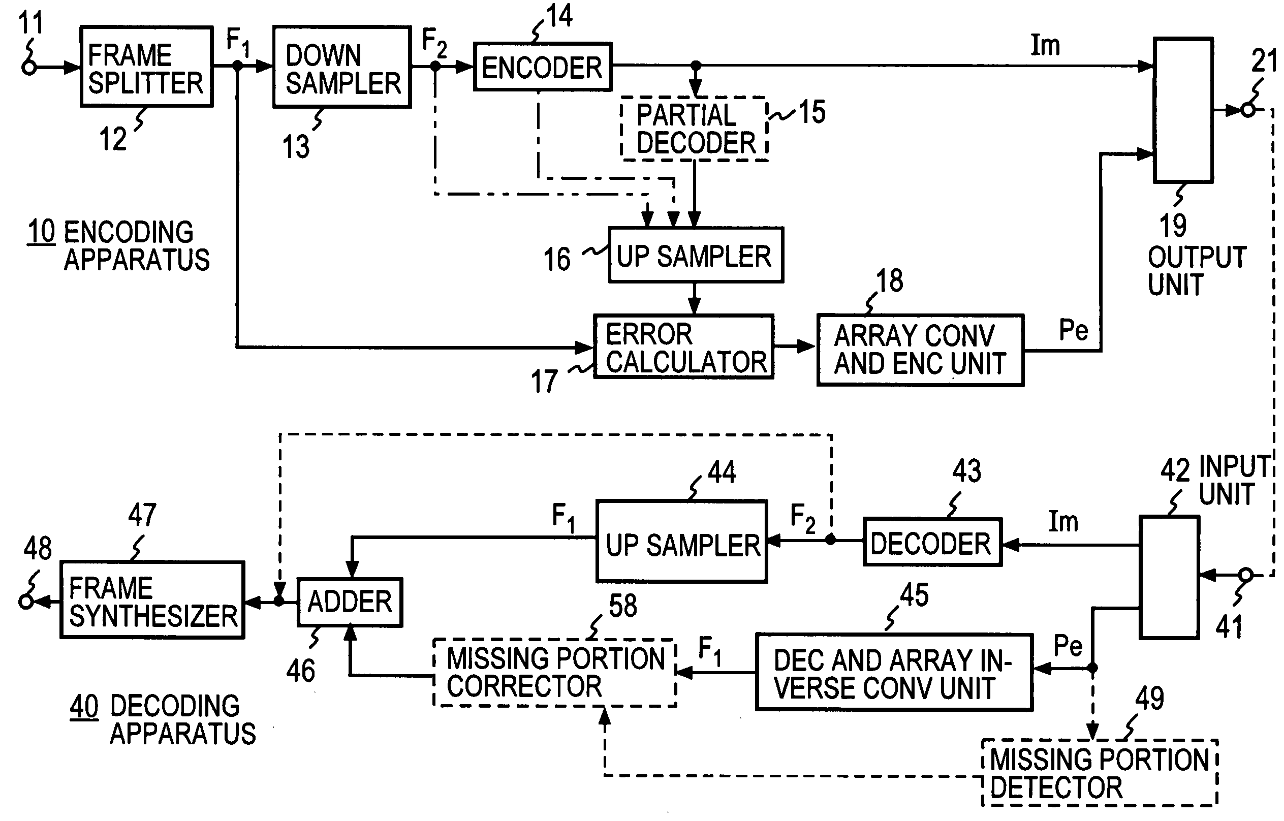
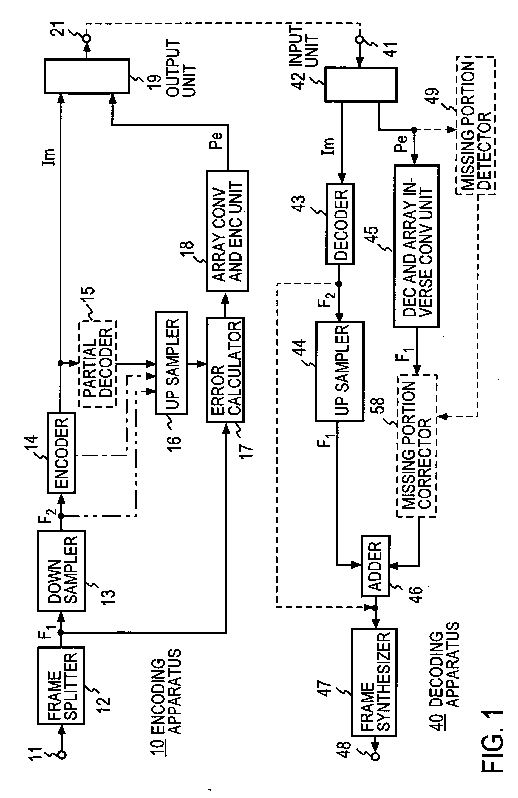
[0119] A first embodiment of the present invention will now be discussed with reference to FIG. 1. As shown, a sampling rate (frequency) is also represented by symbols. A digital signal from an input terminal 11 is split every frame unit, for example, every 1024 samples, by a frame splitter 12, and the digital signal at a first sampling frequency F1 is converted to a digital signal at a second sampling frequency F2 lower than the first sampling frequency F1 by a down sampler 13. In such a case, a low-pass filtering process removes a component in frequency equal to or higher than frequency F2 / 2 so that a loop-back signal may not be caused by the sampling at the second sampling frequency F2.

[0120] An encoder 14 lossy or lossless compression encodes the digital signal at the second sampling frequency F2 and outputs a resulting signal as a main code Im. If the encoder 14 performs a lossy compression encoding operation, the main code Im is decoded by a partial decoder 15. The decoded pa...

second embodiment

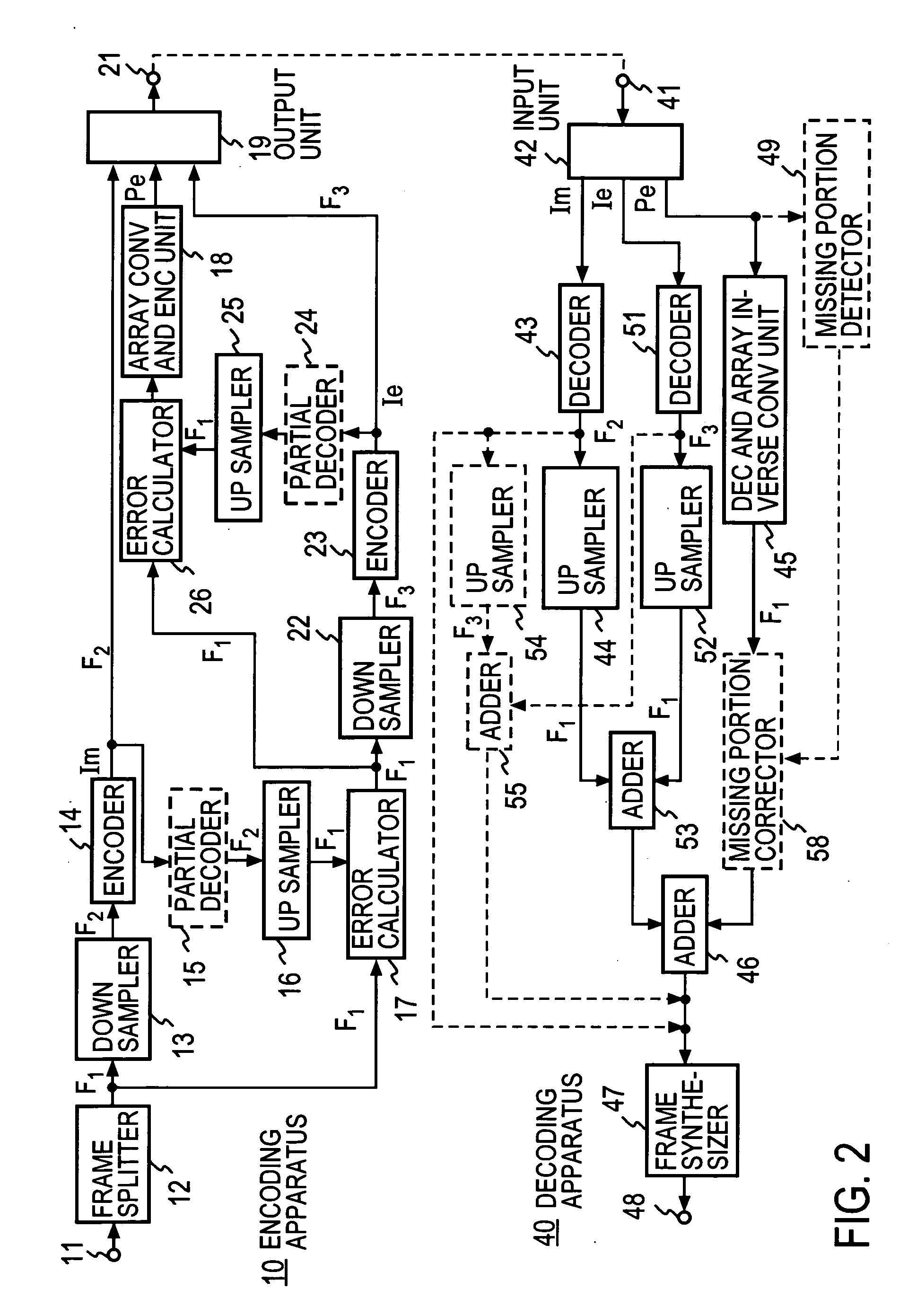
[0128] In accordance with a second embodiment of the present invention, the sampling frequency of a data signal is arranged in multi-layers, and signals of more types of qualities are selectively provided.

[0129] As shown in FIG. 2, elements identical to those described with reference to FIG. 1 are designated with the same reference numerals. In accordance with the second embodiment, a down sampler 22 down samples the error signal at the first sampling frequency F1 from the error calculator 17 to an error signal at a third sampling frequency F3 lower than the first sampling frequency F1 but higher than the second sampling frequency F2.

[0130] For example, the down sampler 13 lowers the first sampling frequency F1 of the input signal to one quarter, thereby resulting in the third sampling frequency F3. The down sampler 22 lowers the second sampling frequency F2 of the error signal to half, thereby resulting in the sampling frequency F3. In other words, the sampling frequencies are re...

third embodiment

[0179] In the embodiments of FIGS. 1, 2, and 3, the array converting and encoding unit 18 array converts and encodes the error signal from the error calculator 17 or 26. Alternatively, the predictive error of the error signal may be array converted and encoded. FIG. 9 illustrates the arrangement in which such a technique is applied to the encoding apparatus 10 of FIG. 1, and the structure of the decoding apparatus 40 corresponding to thereto.

[0180] In that arrangement, a predictive error generator 31 is provided in the encoding apparatus 10 of FIG. 1 between the error calculator 17 and the array converting and encoding unit 18, and a prediction synthesizer 56 is provided in the decoding apparatus 40 between the decoding and array inverse converting unit 45 and the adder 46. The rest of the arrangement remains unchanged from FIG. 1.

[0181] As shown in FIG. 10A, the predictive error generator 31 includes a prediction analyzer 31A, a sample register 31B, a linear predictor 31C, an int...


PUM


Abstract

A down sampler 13 down samples a digital signal in the sampling frequency thereof from 96 kHz to 48 kHz on a frame-by-frame basis. The converted signal is compression encoded and output as a main code Im. An up sampler 16 converts a partial signal corresponding to the main code Im to a signal having the original sampling frequency 96 kHz, for example. An error signal between the up sampled signal and an input digital signal is generated. An array converting and encoding unit 18 array converts bits of sample chains of the error signal, thereby outputting an error code Pe. On a decoding side, a high fidelity reproduced signal is obtained based on the main code Im and the error code Pe, or a reproduced signal is obtained based on the main code Im only.

Description

TECHNICAL FIELD [0001] The present invention relates to a method, an apparatus, and a program for converting a digital signal such as voice, music, and images into a code compressed in a small amount of information, and a method, an apparatus, and a program for decoding the code. BACKGROUND ART [0002] Available as methods for compressing information such as voice and images are a lossy encoding method that permits distortion and a lossless encoding that does not permit distortion. Various lossy compression methods are known based on standards of ITU-T (International Telecommunications Union-Telecom Standardization) or ISO / IEC MPEG (International Organization for Standardization / International Electrotechnical Commission Moving Picture Experts Group). The use of these lossy compression methods allows a digital signal to be compressed to {fraction (1 / 10)} or less while controlling distortion to a minimum. However, the distortion depends on encoding conditions and input signals, and th...

Claims


Application Information

Patent Timeline
IPC IPC(8): G10L19/00
CPCG10L19/0017G10L19/00
Inventor MORIYA, TAKEHIROJIN, AKIOIKEDA, KAZUNAGAMORI, TAKESHI
Owner NIPPON TELEGRAPH & TELEPHONE CORP
Why Eureka
Try Eureka