Oil separator for vehicle air system

a technology of oil separator and vehicle air system, which is applied in the direction of liquid degasification, auxillary pretreatment, separation process, etc., can solve the problems of affecting the performance of air dryer, affecting the performance of compressor, and affecting the flow of air through the air brake system

Inactive Publication Date: 2005-05-05
BENDIX COMML VEHICLE SYST LLC
View PDF30 Cites 16 Cited by
  • Summary
  • Abstract
  • Description
  • Claims
  • Application Information

AI Technical Summary

Problems solved by technology

An oil separator may significantly restrict the flow of air through the air brake system if it becomes clogged with carbon from the oil in the compressed air.
Restricting the flow of air causes significant back pressure which can cause damage to the compressor.
Too much oil, or even small amounts of oil, inside the air dryer will negatively affect the performance of the air dryer and increase the frequency of the maintenance service required on the air dryer.
Oil that is removed from the system is typically dumped or wasted, which can be costly and environmentally damaging.

Method used


Image

  • Oil separator for vehicle air system
  • Oil separator for vehicle air system
  • Oil separator for vehicle air system

Examples


Embodiment Construction

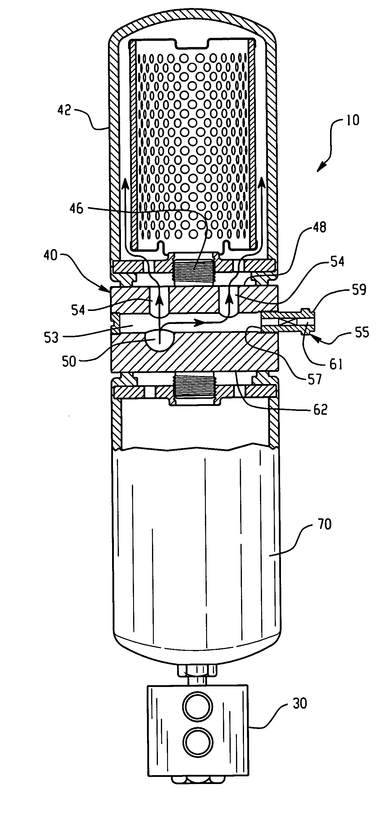
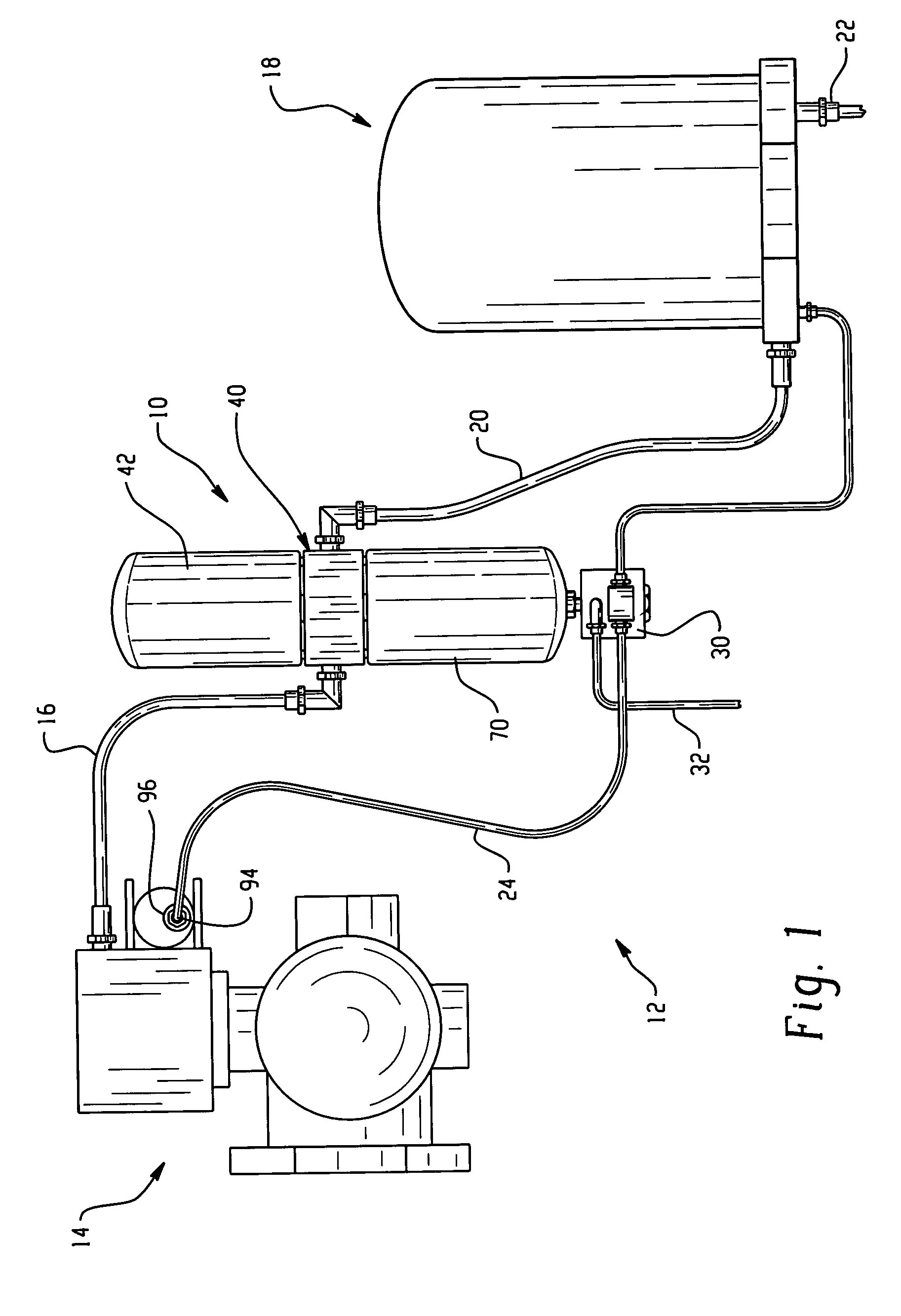
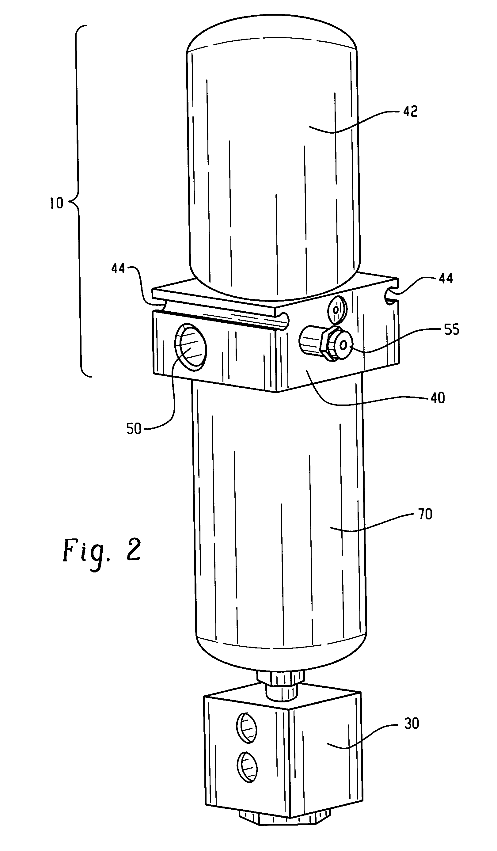
[0020] The present invention relates to a vehicle air system and specifically to an oil separator for removing oil from compressed air used in the system. The present invention is applicable to oil separators of varying constructions. As representative of the invention, FIG. 1 illustrates an oil separator 10 constructed in accordance with a first embodiment of the invention.

[0021] The separator 10 forms part of a vehicle air braking system 12. The vehicle braking system 12 also includes a compressor 14. The compressor 14 supplies air to the separator 10 through an air line 16. Clean air from the separator 10 flows to an air dryer 18 through another air line 20. Dry air from the dryer 18 flows to the vehicle brakes (and other accessories) through an outlet fitting 22 on the air dryer. Another air line 24 from the compressor 14 is connected with a recycling valve 30 on the separator 10, to supply a control signal as described below. The system 12 also includes a return oil line 32 ex...


PUM

PropertyMeasurementUnit
pressureaaaaaaaaaa
flow areaaaaaaaaaaa
angleaaaaaaaaaa

Abstract

An oil separator for use in a vehicle air system includes a recycling valve for removing coalesced oil. The recycling valve may include a piston movable in a cylinder in response to a control air pressure to open the recycling valve and thus drain coalesced oil from a sump under the influence of residual air pressure in the sump. The separator may include a fixture for mounting the separator to a vehicle, including a plurality of ports extending from an inlet port for directing air into the cartridge with a combined flow area at least equal to the flow area of the inlet port. The plurality of ports preferably extend at a right angle to the direction of flow of air through the inlet port. A safety relief valve on the separator releases air when the pressure exceeds a predetermined pressure.

Description

FIELD OF THE INVENTION [0001] The present invention relates to a vehicle air system and specifically to an oil separator for removing oil from compressed air used in the system. BACKGROUND OF THE INVENTION [0002] An oil separator is conventionally used with vehicle compressed air systems to clean contaminants, such as lubricating oil, from the air pumped from the compressor. An oil separator may significantly restrict the flow of air through the air brake system if it becomes clogged with carbon from the oil in the compressed air. Restricting the flow of air causes significant back pressure which can cause damage to the compressor. [0003] In addition, the air brake system typically includes an air dryer downstream of the compressor, with a replaceable cartridge. The lifespan of the air dryer cartridge is determined in large measure by how much oil is entrained in the air delivered to the air dryer. Too much oil, or even small amounts of oil, inside the air dryer will negatively affe...

Claims


Application Information

Patent Timeline
Patent Type & Authority Applications(United States)
IPC IPC(8): B60T17/00F16N39/00
CPCB60T17/004Y10S55/19F16N39/002
Inventor FORNOF, WILLIAM P.ASHLEY, GREGORY R.QUINN, LEONARD A.HOFFMAN, FRED W.SMITH, GREGORY C.
Owner BENDIX COMML VEHICLE SYST LLC
Why Eureka
Try Eureka