Roll-up blind with safety cord cover

a safety cord and blind technology, applied in the direction of shutters/movable grilles, door/window protective devices, wing arrangements, etc., can solve problems such as unfavorable design

Inactive Publication Date: 2005-05-05
LIN HENRY
View PDF2 Cites 43 Cited by
  • Summary
  • Abstract
  • Description
  • Claims
  • Application Information

AI Technical Summary

Benefits of technology

[0006] It is an object of the present invention to provide a roll-up blind with a safety arrangement comprising a headrail, a brake mechanism proximate the headrail, a cord having one end passed the brake mechanism to form an operable portion, a shade cloth coupled to the headrail, the shade cloth having a lower end coupled to the other end of the cord, and a plurality of soft cord covers formed on the shade ...

Problems solved by technology

Unfortunately, a child may put the ring on his/her neck prior to pulling either portion of one ends 17.
T...

Method used


Image

  • Roll-up blind with safety cord cover
  • Roll-up blind with safety cord cover
  • Roll-up blind with safety cord cover

Examples


Embodiment Construction

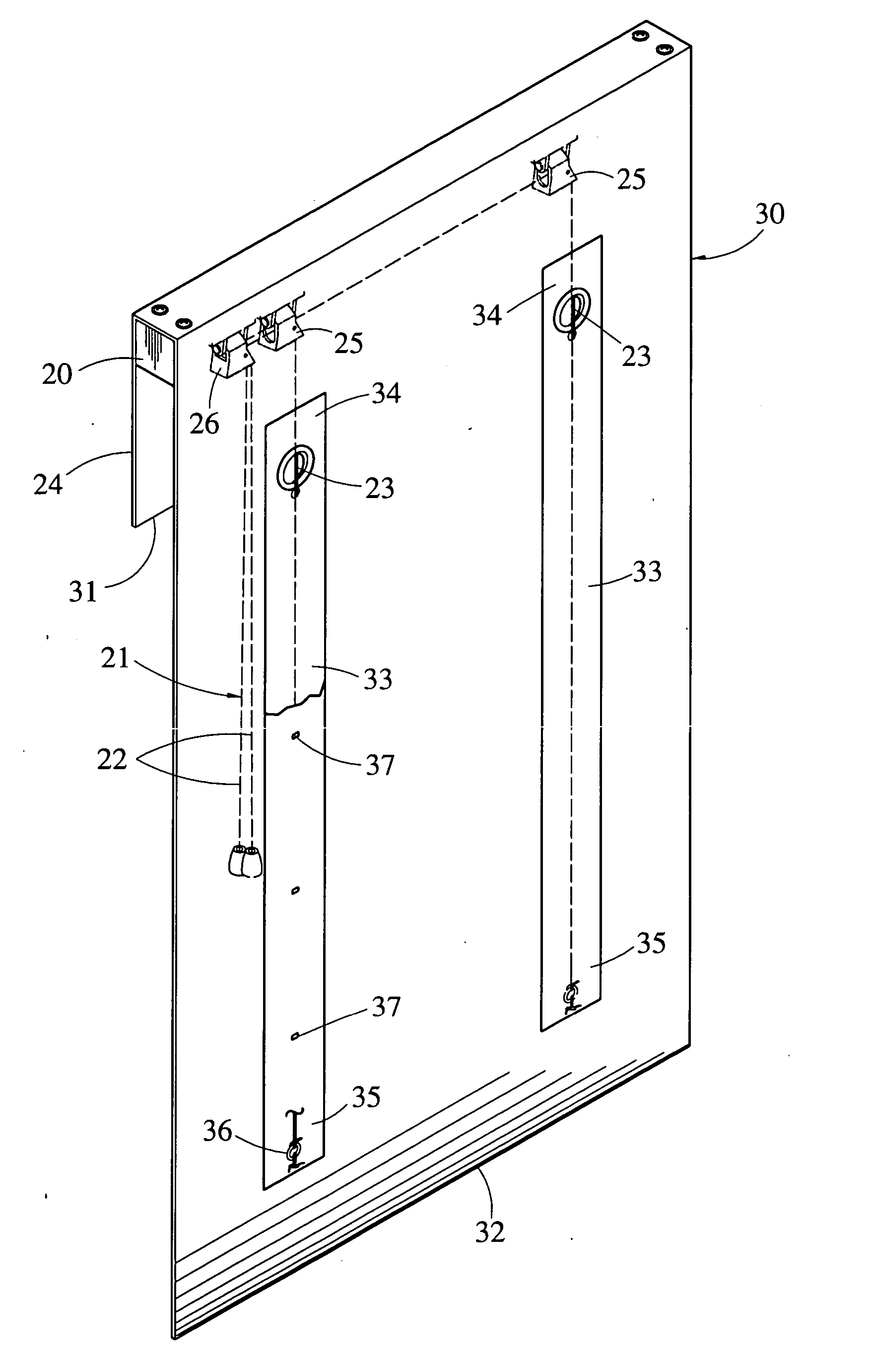
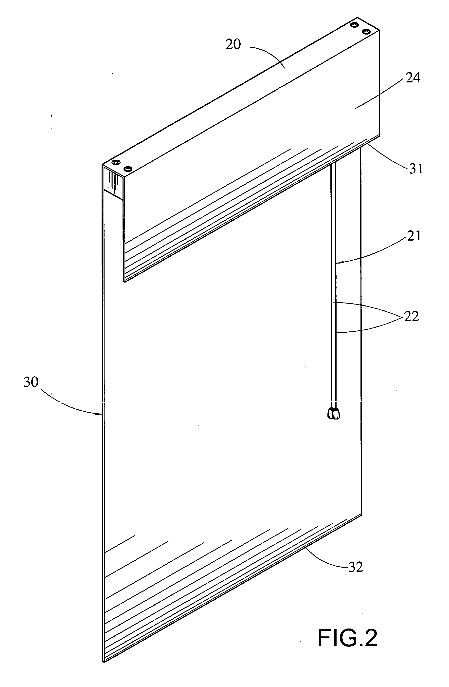
[0014] Referring to FIGS. 2, 3 and 4, there is shown a roll-up blind constructed in accordance with the invention. The blind comprises a headrail 20 coupled to a window, a brake mechanism proximate the headrail 20, the brake mechanism comprising two tension pulley sets 25 and a brake 26 adjacent one tension pulley set 25, and a cord 21 including two portions 22 at one end passing one tension pulley set 25 and the brake 26, and two portions 23 at the other end. In operation, a user can pull either portion 22 to lower or lift the blind. The blind further comprises a shade cloth 30 having a lower end 32 and an upper end 31 stretched over the headrail 20 in which a portion stretched over the headrail 20 is formed as a decorative member 24 terminated at the upper end 31. The decorative member 24 is used to cover an upper portion of the headrail 20 and a joining portion of the headrail 20 and the shade cloth 30. Two cord covers 33 are formed of a soft material (e.g., yarn). Each cord cove...


PUM


Abstract

Disclosed is a roll-up blind with safety arrangement. The blind comprises a headrail, a brake mechanism proximate the headrail, a cord having one end passed the brake mechanism to form an operable portion, a shade cloth coupled to the headrail, the shade cloth having a lower end coupled to the other end of the cord, and a plurality of cord covers formed on the shade cloth to cover the other end of the cord. Whereby pulling the operable portion of the cord will cause the shade cloth to wrinkle upwardly and the cord covers to contract together. Most importantly, a dangerous ring will not be formed by the cord and the cord covers in operation. Also, the shade cloth is wrinkled upwardly and the cord covers are contracted together to form aesthetic members in response to drawing up.

Description

BACKGROUND OF THE INVENTION [0001] 1. Field of the Invention [0002] The present invention relates to roll-up blinds and more particularly to a roll-up blind with a safety cord cover. [0003] 2. Description of Related Art [0004] Blinds for keeping out light are well known. A conventional roll-up blind 10 is shown in FIG. 1. The blind 10 comprises a shade cloth 11, a headrail 12 coupled to a top of the shade cloth 11, a brake 13 coupled to about one end of the headrail 12, and a cord 14 being operative to pull to lower or lift the shade cloth 11 prior to stopping the shade cloth 11 at a predetermined position by means of the brake 13. The headrail 11 comprises a plurality of rectangular sections 15 stitched together longitudinally. Two spaced holes 16 are formed between any two adjacent sections 15. One ends 17 of the cord 14 pass through the brake 13 prior to disposing vertically and the other ends 18 thereof pass the holes 16 to fasten at the lowest holes 16. Hence, the shade cloth 1...

Claims


Application Information

Patent Timeline
IPC IPC(8): E06B9/262
CPCE06B2009/2622E06B9/262
Inventor LIN, HENRY
Owner LIN HENRY
Why Eureka
Try Eureka