
Ceramic/metal composite material brake lining for high-speed train and preparation method of ceramic/metal composite material brake lining

A technology of metal composite materials and high-speed trains, applied to brake parts, friction linings, mechanical equipment, etc., can solve the problems of short life, high wear rate, poor thermal stability, etc., and achieve good wear resistance and heat resistance Recession ability, convenient engineering preparation, and the effect of improving macroscopic uniformity

Active Publication Date: 2013-05-01
浙江天乐新材料科技有限公司
View PDF4 Cites 24 Cited by
  • Summary
  • Abstract
  • Description
  • Claims
  • Application Information

AI Technical Summary

Problems solved by technology

[0006] The purpose of the present invention is to overcome the defects of poor thermal stability, low friction coefficient, high wear rate, poor thermal attenuation resistance and short service life of existing high-speed train brake pads, and to provide a brake pad with good thermal stability, high friction coefficient and wear resistance. Brake pads for high-speed trains with low efficiency, good thermal attenuation resistance and long service life

Method used


Image

  • Ceramic/metal composite material brake lining for high-speed train and preparation method of ceramic/metal composite material brake lining
  • Ceramic/metal composite material brake lining for high-speed train and preparation method of ceramic/metal composite material brake lining
  • Ceramic/metal composite material brake lining for high-speed train and preparation method of ceramic/metal composite material brake lining

Examples


Embodiment 1

[0036] Example 1: Preparation method of columnar array conjoined SiC ceramic block reinforced copper-based composite brake sheet

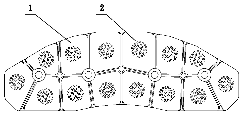
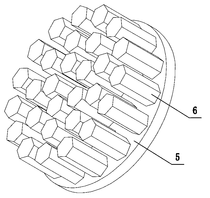
[0037] Step 1: Preparation of SiC ceramic blocks in a columnar array: According to the requirements, obtain a circular SiC ceramic column 6 with a cross section of 3 and a rectangle with a longitudinal section of 4×10, with a column spacing of 3 mm, along the x-axis and In the y-axis equidistant array mode, the thickness of the ceramic substrate 5 is 2.5 mm. According to the shrinkage rate of silicon carbide sintering is 17~20%, a suitable gypsum female mold is prepared, and the silicon carbide slurry prepared according to a certain proportion is placed in the female mold, and the conjoined ceramic element is obtained by grouting. Blank. Dry the conjoined ceramic green body, modify the shape, polish, and adopt a pressureless sintering process at 1950-2100 ℃, and keep it warm for 30-60 minutes to obtain a ceramic block.

[0038] Step 2: Surface tr...

Embodiment 2

[0043] Embodiment 2: columnar array conjoined B 4 Preparation method of C ceramic block reinforced copper-based composite material brake sheet

[0044] Step 1: Cylindrical Array Conjoint B 4 Preparation of C ceramic block: According to the requirements, obtain a hexagonal cross-section with a side length of 3 mm and a height of 12 mm. 4 C Ceramic pillars 6, the distance between pillars is 4 mm, arrayed at equal intervals along the x-axis and y-axis, the thickness of the ceramic substrate 5 is 2 mm, according to B 4 C The shrinkage rate during sintering is 18~22%, and a suitable steel mold is prepared. B will be prepared according to a certain proportion and granulated 4 C powder is put into the female mold, and the green body is taken out after forming with a pressure of 100 ~ 200 MPa, put into a soft mold cover and then formed by isostatic pressing at a pressure of 150 ~ 250 MPa to obtain a conjoined ceramic green body? The bulk ceramic green body is dried, trimmed, polis...

Embodiment 3

[0050] Example 3: Columnar array conjoined TiB 2 Preparation method of ceramic block reinforced iron-based composite brake pad

[0051] The difference from Example 1 is that TiB 2 The cross section of the ceramic block is an ellipse with different length-to-diameter ratios and a rectangle with a longitudinal section of 3×12. The column spacing is 3 mm. The ceramic substrate 5 has a thickness of 3 mm. Casting 20Cr steel in TiB with column array conjoined by negative pressure-electromagnetic field co-casting method 2 In the preheated film-coated sand mold casting cavity of the ceramic block, the ceramic array and steel are combined into one body to obtain the gate plate. Negative pressure-electromagnetic field combined casting improves the fluidity and filling ability of the melt, refines the grains, and greatly reduces the defects of castings. After precision machining and quenching + annealing heat treatment, the strength of the aluminum base reaches 375 MPa.

[0052] Afte...


PUM

PropertyMeasurementUnit
thicknessaaaaaaaaaa
breaking strengthaaaaaaaaaa
thicknessaaaaaaaaaa

Abstract

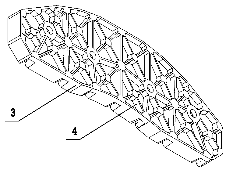
The invention provides a ceramic / metal composite material brake lining for a high-speed train and a preparation method of the ceramic / metal composite material brake lining, and belongs to the technical field of high-speed brake. The existing high-speed train brake lining has the defects that the thermal stability is poor, the friction factor is low, the abrasion rate is high, the thermal decay resistance is poor, and the service life is short. The ceramic / metal composite material brake lining comprises friction blocks, a base plate and a heat radiation fin, wherein the friction blocks are made of ceramic block reinforced metal composite materials, the gap width among the friction blocks is 3 to 8mm, the ceramic block is obtained through sintering ceramic posts of a certain rule and connected ceramic biscuits of ceramic substrates connected with the ceramic posts, and the connected ceramic biscuits can be formed in modes of slurry filling, gel mold filling, molding pressing, isostatic pressing and the like. The preparation method provided by the invention comprises the following steps including ceramic block sintering, surface treatment, brake lining casting, precise processing and heat treatment. The ceramic / metal composite material brake lining has the characteristics that the thermal stability is good, the friction factor is high, the abrasion rate is low, the thermal decay resistance is good, the service life is long, and the like, and the effective braking can be realized on 380km / h high-speed trains.

Description

technical field [0001] The invention belongs to the technical field of high-speed braking, and in particular relates to a brake pad for high-speed trains and a preparation method thereof. Background technique [0002] The braking performance of high-speed train brake pads directly affects the safety of train operation, so higher requirements are put forward for the braking performance of brake pads, especially the tribological performance? With the rapid development of high-speed railways in my country, the speed of trains has exceeded 350 km / h, the traditional resin-based semi-metal and powder metallurgy method to prepare cermet sintered brake materials can no longer meet the requirements of emergency braking above 350 km / h. This is because the thermal conductivity of synthetic resin brake material friction pads is low. When the braking temperature exceeds 350 °C, the resin is prone to carbonization, resulting in cracking and failure of the friction pads; iron-based and co...

Claims


Application Information

Patent Timeline
Patent Type & Authority Applications(China)
IPC IPC(8): F16D65/04F16D69/02B22D19/02B22D19/08
Inventor 房明喻亮葛锦明张显南俞晓祥
Owner 浙江天乐新材料科技有限公司
Learn More