
Dual-bearing reel brake device and drag cover attachment structured therefor

Inactive Publication Date: 2002-07-02
SHIMANO INC
View PDF8 Cites 24 Cited by
  • Summary
  • Abstract
  • Description
  • Claims
  • Application Information

AI Technical Summary

Benefits of technology

is to structure a drag cover attachment that can be readily attached with precision, and that limits increase in spool inertia.
According to a further aspect of the present invention, because the centering part is tightly fitted to the circular groove part, the drag cover can be centered concentrically with the rotating member just by assembling the drag cover. In addition, because the drag cover is assembled with screw members, it is easy to control the tightening torque. For this reason, the drag cover can be precisely and easily assembled on the rotating member. In addition, because the drag cover is assembled with screw members, it is no longer necessary to form thick screw parts on the outer peripheral part of the drag cover and the outer peripheral side of the rotating member, and the increase of spool inertia can be suppressed.

Problems solved by technology

This seems to be because the axial behavior of the brake disk is unstable due to the fact that the brake disk is shiftable axially as fitted to the spool.
Controlling the tightening torque is therefore difficult, and water is permitted to intrude simply by the cover becoming loose, or if it otherwise will not loosen the disks cannot be serviced.
In addition, wobble in the screw makes it difficult to center the drag cover accurately on the spool.
In particular, in large-scale trolling reels that have a large diameter spool, it is even more troublesome to control the tightening torque and hard to conduct accurate centering.
For this reason, it is difficult to attach the drag cover readily onto the spool with precision.
Further, the fact that the portion where the male and female threads screw together is formed on the outermost periphery of the spool, or of a component that rotates unitarily with the spool, means that portion necessarily will be thick, which increases the inertia of the spool.

Method used


Image

  • Dual-bearing reel brake device and drag cover attachment structured therefor
  • Dual-bearing reel brake device and drag cover attachment structured therefor
  • Dual-bearing reel brake device and drag cover attachment structured therefor

Examples


Embodiment Construction

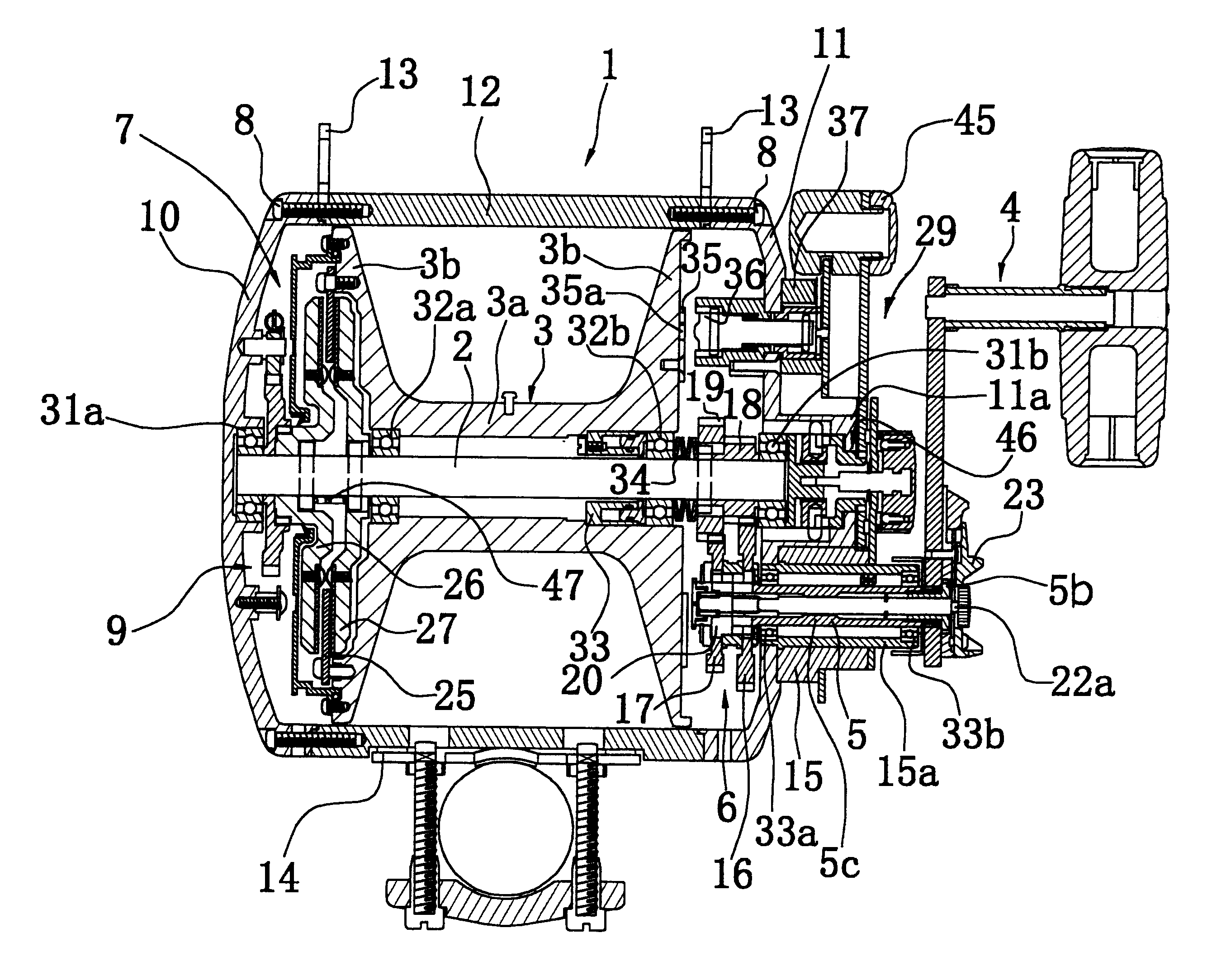
(a) The position for mounting the drag cover 41 is not limited to the end surface of the side of the spool 3 away from the handle 4, and is determined by the mounting position of the lever drag mechanism 7. Specifically, if the lever drag mechanism is on the handle 4 side, the drag cover 41 is mounted on the handle 4 side of the spool 3.

(b) The rotating part is not limited to the spool 3 itself, and includes, for example, the case member, etc. that is provided on the spool spindle 2 such that it rotates as a single unit with the spool 3. The structure wherein the drag cover is assembled on this case member is also included in the present invention.

(c) As indicated in FIG. 8, in order to make it easy to mount the O-ring 42, a ring-shaped mounting groove 41f that can stop the O-ring 42 on the centering portion 41c may also be provided. When providing this kind of mounting groove 41f, it is difficult for the O-ring 42 to move, and therefore the assembly operation for the drag cover 41 ...


PUM


Abstract

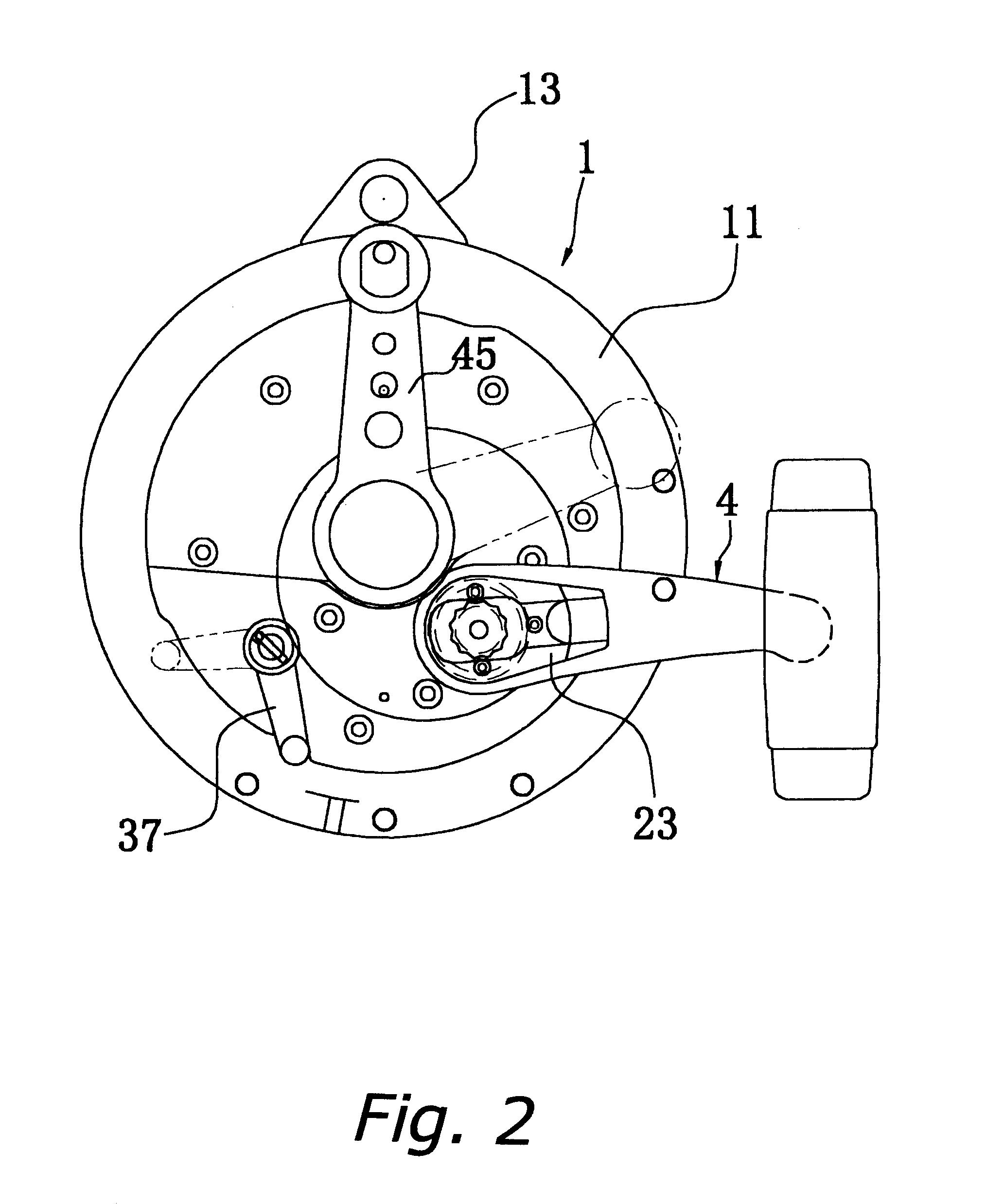
A double-drag type lever-drag mechanism for a double-bearing trolling reel. The drag mechanism is configured to improve overall reel braking and drag performance by securing the brake release state reliably and by a design that curbs increase in spool inertia and provides for ease of operation and precision in attaching the drag cover. The lever drag mechanism 7 brakes the spool 3 rotation in the line spool-out direction, and is equipped with a brake disk 25 non-rotatably fitted to one end of the spool such to be axially shiftable a predetermined distance. Sandwiching the brake disk 25 between friction disk 26, immobilized against axially outward movement, and axially shiftable friction disk 27 rotates the drag / brake disks 25-27 unitarily with the spool 3. Against the spool 3 a coil spring 28 urges the brake disk 25 away from the spool 3. A shifting mechanism 29 reciprocates the spool 3 and drag / brake disks 25-27 axially. The mounting configuration for the drag cover includes a circular groove 3c radially beyond which is a plurality of circumferentially spaced threaded holes 3d in the end face of the spool 3; a tubular centering portion 41c that snugly fits into the circular groove 3c, radially extending from which is a ring-shaped mounting portion 41b; an O-ring 42 in the circular groove 3c making sealing contact circumferentially with the tubular centering portion 41c; and a plurality of machine screws 44 passing through-holes in the mounting portion 41b and screwed into the threaded holes 3d.

Description

1. Technical FieldThe present invention concerns fishing reel brake devices and associated drag cover attachments for the spool rotation transmitting mechanism that transmits to the spool rotation from the handle mounted rotatably on the reel main unit. More particularly, the invention relates to a dual-bearing reel brake device provided in the course of the rotation transmitting mechanism for braking rotation in the line spool-out direction, and to drag covers non-rotatably mounted laterally of, and at a spacing from, the spool to house its drag disk.2. Description of Related ArtOne class of dual-bearing reels that is known is the trolling reels, which are reels for catching large fish. The trolling reel is provided with a spool around the perimeter of which is wound fishing line, a spool spindle that supports the spool, and a reel main unit that centrally supports the spool spindle. Provided on the reel main unit is a handle spindle that is disposed such that it is parallel to the...

Claims


Application Information

Patent Timeline
IPC IPC(8): A01K89/00A01K89/015
CPCA01K89/015A01K89/01916A01K89/01928A01K89/045
Inventor IKUTA, TAKESHI
Owner SHIMANO INC
Learn More