
Apparatus and method for intermodal conversion of transport vehicles; rail-to-highway and highway-to-rail

Inactive Publication Date: 2007-04-26
SPROAT WILLIAM HARVEY
View PDF0 Cites 21 Cited by
  • Summary
  • Abstract
  • Description
  • Claims
  • Application Information

AI Technical Summary

Benefits of technology

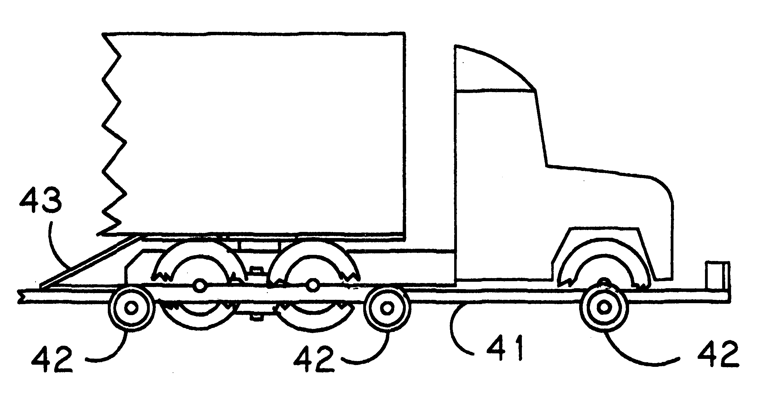
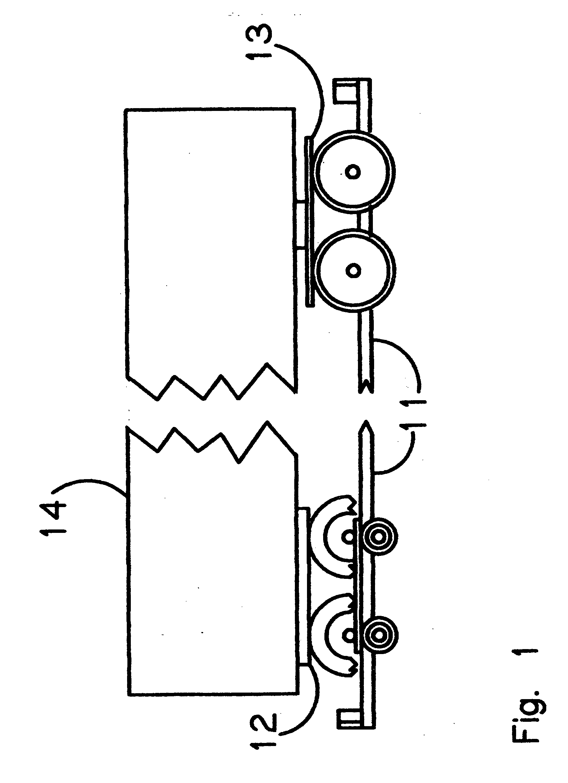
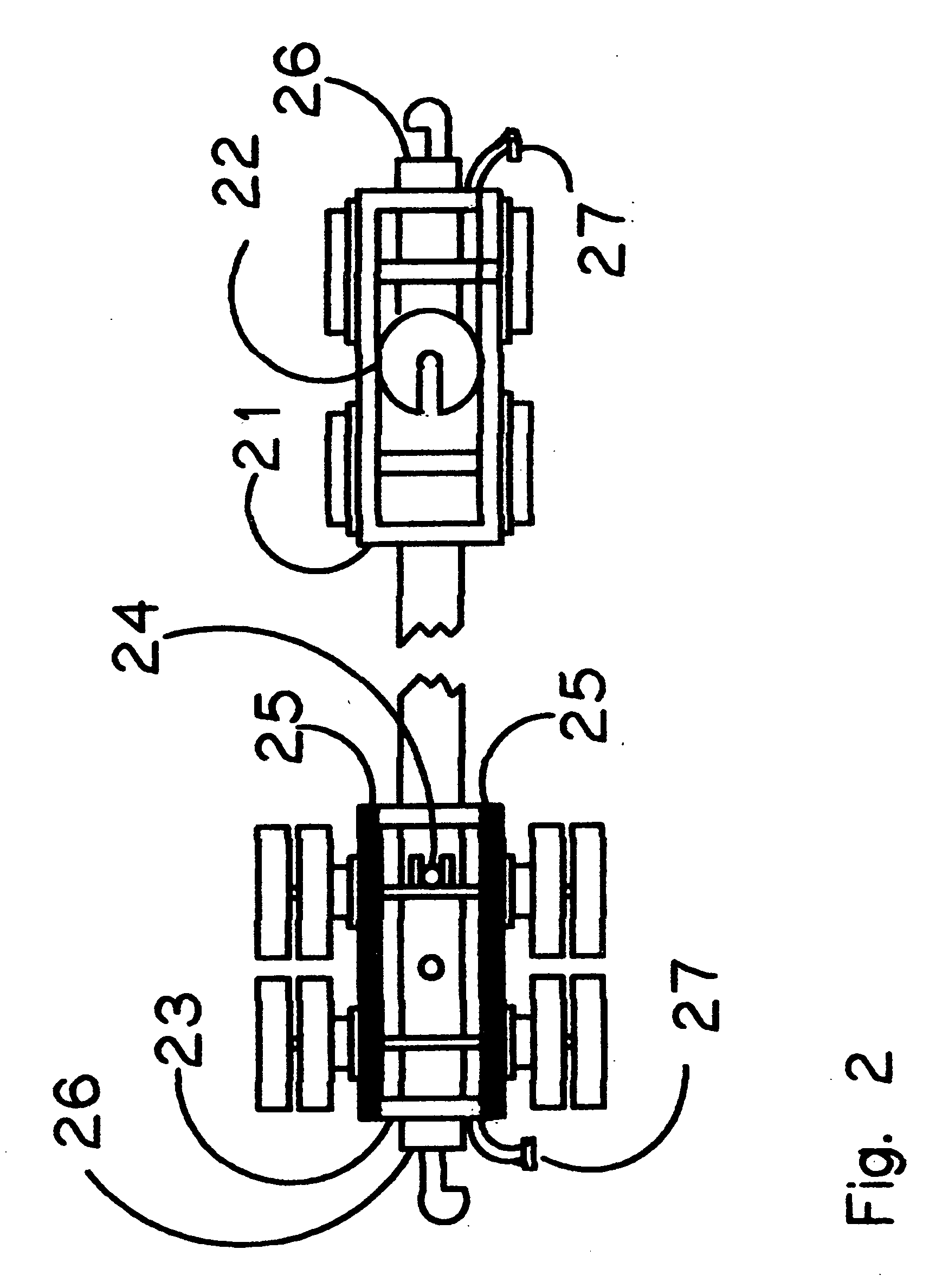
[0011] The primary object of the invention is to provide an economical means to conduct reversible intermodal conversion of vehicles, without fixed mechanical infrastructure or add-on systems, from highway-to-rail from paved rail stages; such conversion affording both rail transport efficiencies and highway routing flexibility. Another object of the invention is to reduce transport fuel consumption by replacing pneumatic tire drag with solid wheels-on-rails and to afford close proximity inter-vehicle drafting to reduce air drag. Another object of the invention is to reduce fuel consumption at by eliminating highway braking, acceleration and periodic stops at engine idle. A further object of the invention is to improve overall delivery time at by avoiding traffic delays. Yet another object of the invention is to reduce accident liability exposure by avoiding highway encounters. Still yet another object of the invention is to enable highway-to-rail and rail-to-highway transition without a mechanized vehicle handling infrastructure or vehicle modifications.

Problems solved by technology

However, rail transport in the U.S. is declining because it relies on a cumbersome infrastructure of depots or marshalling yards which impose lost time in train makeup, and cost and time penalties for materials handling.
However, highway transport is now seeing drawbacks by virtue of its popularity.
Roads are more congested with semi tractor-trailers, accidents are frequent, and fuel demand is driving up costs.
Technology to directly adapt highway vehicles to rails has realized limited routine use in railway maintenance vehicles.
Rigidly attached highway vehicle rail adapters are limited to short runs at low speed operation because there is no shock absorbing suspension, and they require an added hydraulic system for actuation.
A bogie equipped sub-frame variant of this approach provides suspension, but adds significant weight.
Further, most adapters do not offer sufficient draft load transfer capabilities necessary for multi-vehicle train configurations.
Dedicated rail cars outfitted for highway freight trailer transfer are an expensive capital investment for single purpose use.
Furthermore, this mode of rail transfer requires limited “on-time”, fixed terminal handling facilities to on-load and off-load freight trailers.
Both expense and lack of routing flexibility make this option unattractive.

Method used


Image

  • Apparatus and method for intermodal conversion of transport vehicles; rail-to-highway and highway-to-rail
  • Apparatus and method for intermodal conversion of transport vehicles; rail-to-highway and highway-to-rail
  • Apparatus and method for intermodal conversion of transport vehicles; rail-to-highway and highway-to-rail

Examples


Embodiment Construction

[0026] Detailed descriptions of the preferred embodiment are provided herein. It is to be understood, however, that the present invention may be embodied in various forms. Therefore, specific details disclosed herein are not to be interpreted as limiting, but rather as a basis for the claims and as a representative basis for teaching one skilled in the art to employ the present invention in virtually any appropriately detailed system, structure or manner.

[0027] In the illustrated and described embodiment of this invention, both apparatus and method for vehicle intermodal transition, highway-to-rail and rail-to-highway, are presented. The purpose of the invention is to afford the flexibility of selecting highways leading from origin and to destination, while providing the economy of rail operation for overland expanses of the route. This is accomplished by staging inter-modal transition at rail grade crossings or paved rail spurs without need for a fixed mechanized infrastructure, o...


PUM


Abstract

This invention is an apparatus and method for reversible intermodal conversion of transport tractors and trailers, highway-to-rail. Trailer add-ons are wheel mount shims and an axle housing draft sill pin receptacle. No add-ons are required for tractors. Highway-to-rail conversion involves securing a rail interface apparatus, consisting of rail carriage assemblies, bogies, and end coupler draft sills beneath each vehicle to align and bear loads-to-rails, and to provide draft load transfer. Staging is on paved grade slightly above rail level. Vehicle conversion is made without loading / unloading mechanized infrastructure, add-on weight, wheel removal, or powered actuators. Full use of inherent vehicle suspension and anti-roll devices is afforded. Draft sills, pneumatic brake lines, and knuckle couplers are employed for train configurations. Draft may be afforded by either a locomotive or a rail converted highway tractor.

Description

[0001] An apparatus and method for inter-modal conversion of transport vehicles; rail-to-highway and highway-to-rail. CROSS REFERENCE TO RELATED APPLICATIONS [0002]U.S. Patent Documents4385857May 1983Willetts410 / 534452147June 1984Jwuc105 / 4.24547107October 1985Krause410 / 584597337July 1986Willetts105 / 4.14665834May 1987van Iperen105 / 4.14669391June 1987Wicks, et al.105 / 4.34685399August 1987Baker105 / 4.14766818August 1988Wicks, et al.105 / 4.34838744June 1989Bakka, et al.410 / 534841872June 1989Wicks, et al.104 / 4.34907514March 1990Wicks, et al.105 / 4.34922832May 1990Lienard, et al.105 / 4.25040466August 1991Wicks, et al.105 / 4.35537931July 1996Donkin105 / 1595826517October 1998Larson, et al.105 / 4.35890433April 1999Wicks105 / 4.26050197April 2000Wicks105 / 4.26123029September 2000Mobley105 / 4.16199485March 2001Pyle105 / 72.26263801July 2001Eckelberry105 / 215.26736071May 2004Engle105 / 238.1Statement Regarding Federally Sponsored Research or Development [0003] Not Applicable Description of Attached Appendix [0...

Claims


Application Information

Patent Timeline
IPC IPC(8): B61C15/00
CPCB60F1/046B61D3/184
Inventor SPROAT, WILLIAM HARVEY
Owner SPROAT WILLIAM HARVEY
Learn More