Al technical title is built by PatSnap Al team. It summarizes the technical point description of the patent document.
a brake and mobile technology, applied in the field of mobile scaffolding, can solve the problems of prior art brakes that cannot be activated by workers, scaffolding to roll undesiredly, and problems such as the inability of workers to activate prior art brakes,
Inactive Publication Date: 2005-03-08
GRANITE IND
View PDF8 Cites 25 Cited by
Summary
Abstract
Description
Claims
Application Information
AI Technical Summary
This helps you quickly interpret patents by identifying the three key elements:
Problems solved by technology
Method used
Benefits of technology
The present invention provides an improved scaffolding brake that does not suffer from the problems and limitations of the prior art brakes detailed above. The inventive brake enables a worker supported on the scaffolding platform to selectively activate the brake while supported on the support platform to restrain motion of the scaffolding and thereby prevent unsafe and inadvertent motion of the scaffolding while the worker is supported thereon.
Problems solved by technology
These prior art caster brakes are problematic and have several undesirable limitations.
For example, the prior art brakes cannot be activated by a worker while the worker is supported on the scaffolding platform.
The prior art caster brakes undesirably require the worker to either repeatedly climb up and down the scaffolding to set and unset the brake or require two workers (e.g., one to do the tile work on the platform and one to operate the brake from the ground) to perform the same amount of work a single worker could otherwise accomplish in the same span of time.
It has further been determined that unsafe working conditions arise when a worker is supported on the scaffolding platform and the brake is not in a locked position (e.g., if the tile worker previously described fails to set the brake each time) thereby enabling the scaffolding to roll undesirably placing the supported worker in peril of losing balance and / or falling off the scaffolding.
Method used
Image
Click on the blue label to locate the original text in one second.
Reading with bidirectional positioning of images and text.
Examples
Embodiment Construction
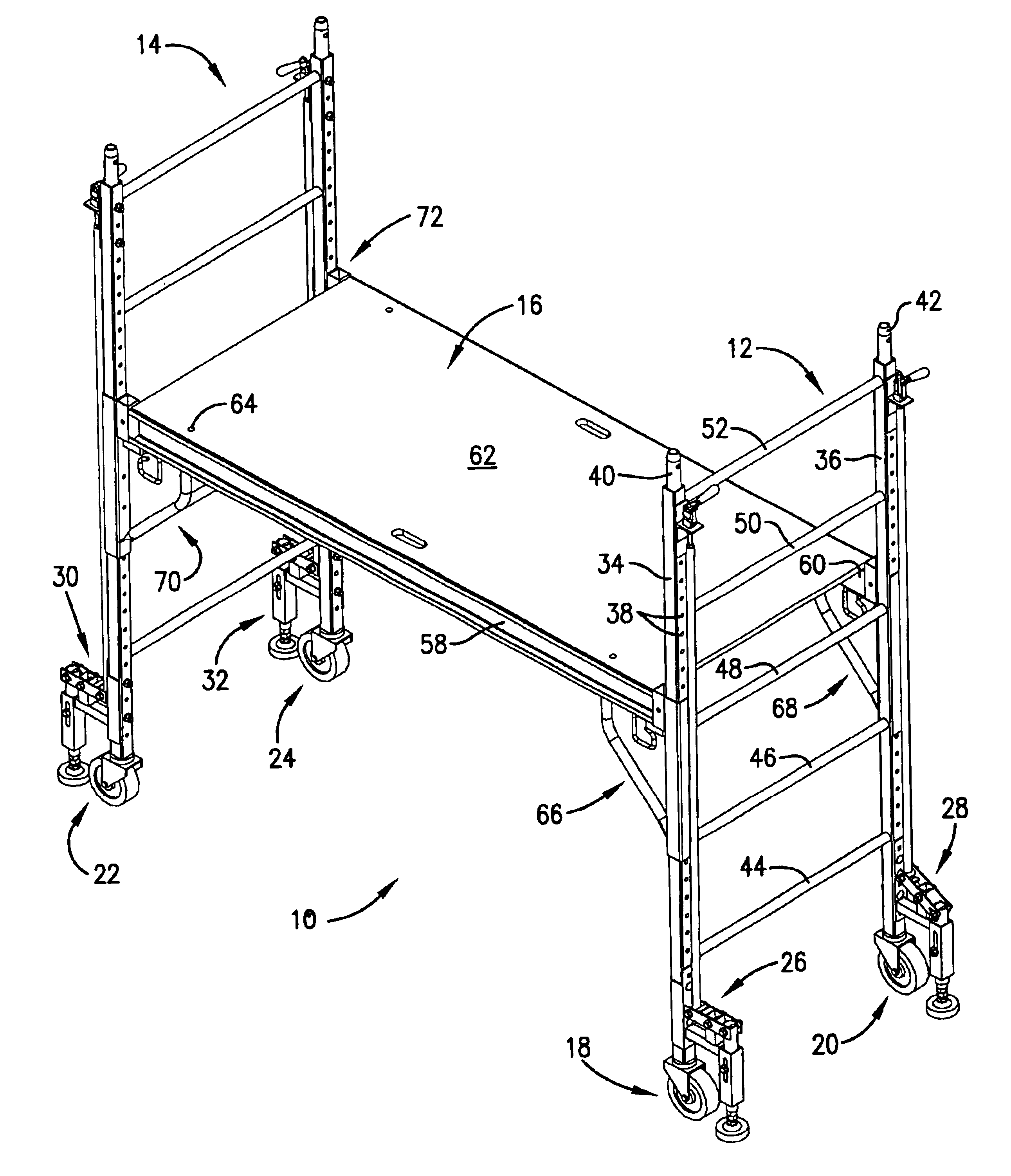
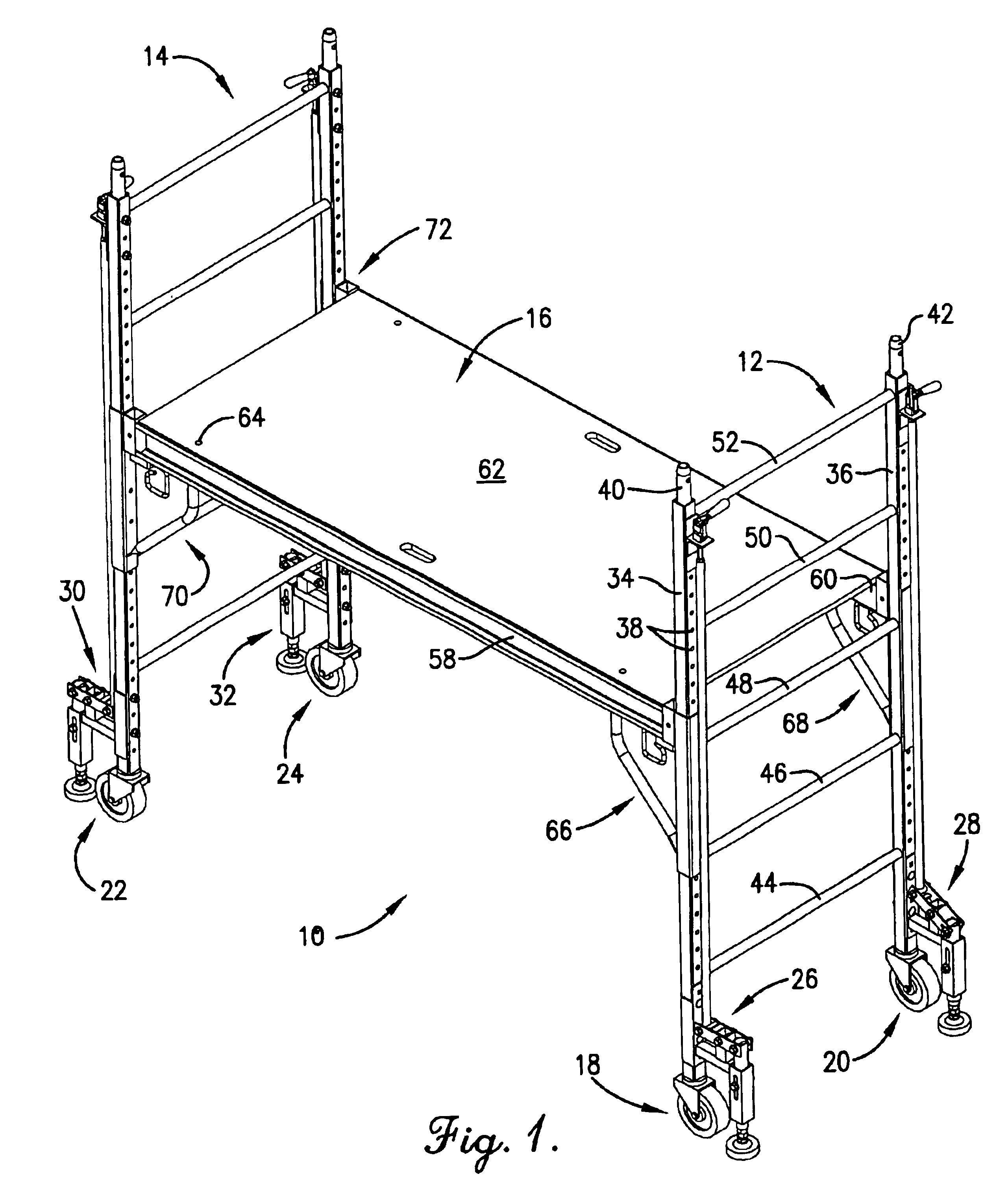
FIG. 1 illustrates a mobile scaffolding 10 constructed in accordance with a preferred embodiment of the present invention and configured for elevating a worker (not shown) above a floor or ground surface S (see FIGS. 2-4). The illustrated scaffolding 10 utilizes a pair of rollable ladder-type frames to support a vertically-adjustable platform therebetween. However, the principles of the present invention are not limited to this scaffolding configuration and equally apply to virtually any type of scaffolding so long as the scaffolding supports an elevated worker and is movable (e.g., rollable, etc.). The illustrated scaffolding 10 broadly includes a pair of frames 12 and 14, a platform 16 supported by the frames 12,14, a pair of casters 18, 20 and 22, 24 rollably supporting a respective one of the frames 12,14, and a brake assembly 26, 28, 30, and 32 associated with a corresponding one of the casters 18,20,22,24, respectively.
In more detail, each of the frames 12,14 is configured to ...
PUM
Abstract
A mobile scaffolding (10) for elevating a worker (not shown) above a floor or ground surface (S) is disclosed. The scaffolding (10) broadly includes a pair of frames (12) and (14), a platform (16) supported by the frames (12,14), a pair of casters (18, 20) and (22,24) rollably supporting a respective one of the frames (12,14), and a brake assembly (26, 28,30, and 32) associated with a corresponding one of the casters (18,20,22,24), respectively. The inventive brake assemblies (26,28,30,32) enable the worker supported on the platform (16) to selectively activate and deactivate the respective brake assemblies (26,28,30,32) from the platform (16). This enables the worker supported on the platform (16) to deactivate the brake assemblies (26,28,30,32), reposition the scaffolding (10), and then reactivate the brake assemblies (26,28,30,32) without requiring the worker to dismount from the platform (16).
Description
BACKGROUND OF THE INVENTION1. Field of the InventionThe present invention relates generally to mobile scaffolding. More specifically, the present invention concerns a mobile scaffolding brake that can be activated from the support platform and when activated restrains motion of the scaffolding. The inventive brake enables a worker supported on the scaffolding platform to selectively prevent unsafe and inadvertent motion of the scaffolding while the worker is supported thereon.2. Discussion of Prior ArtIt is known in the art to utilize scaffolding to provide an elevated work platform to elevate a worker above a floor or ground surface to complete a task (e.g., painting, drywall finishing, etc.). The scaffolding utilized to provide the elevated work platform is often mobile scaffolding that can be quickly and easily moved from one working position to the next. For example, it is known in the art to support a scaffolding frame with one or more casters that enable the assembled scaffold...
Claims
Application Information
Patent Timeline
Application Date:The date an application was filed.
Publication Date:The date a patent or application was officially published.
First Publication Date:The earliest publication date of a patent with the same application number.
Issue Date:Publication date of the patent grant document.
PCT Entry Date:The Entry date of PCT National Phase.
Estimated Expiry Date:The statutory expiry date of a patent right according to the Patent Law, and it is the longest term of protection that the patent right can achieve without the termination of the patent right due to other reasons(Term extension factor has been taken into account ).
Invalid Date:Actual expiry date is based on effective date or publication date of legal transaction data of invalid patent.