Cap device

a technology of cap and spherical body, which is applied in the directions of transportation and packaging, refuse gathering, mine roof caps, etc., can solve the problems of difficulty in automating such actions in the two different directions, and achieve the effect of easy fixation of linkage members

Active Publication Date: 2005-05-05
TOYODA GOSEI CO LTD
View PDF15 Cites 21 Cited by
  • Summary
  • Abstract
  • Description
  • Claims
  • Application Information

AI Technical Summary

Benefits of technology

[0008] The object of the invention is to provide a cap device having a tether

Problems solved by technology

There is a difficulty in automating such actions in the two different directions, since s

Method used


Image

  • Cap device
  • Cap device
  • Cap device

Examples


Embodiment Construction

[0027] (1) General Structure of Fuel Cap 20

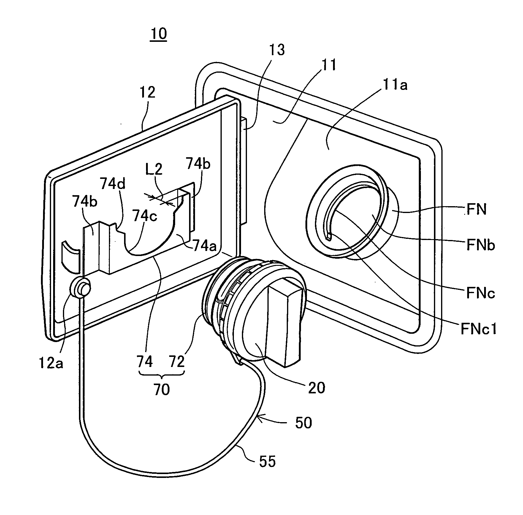
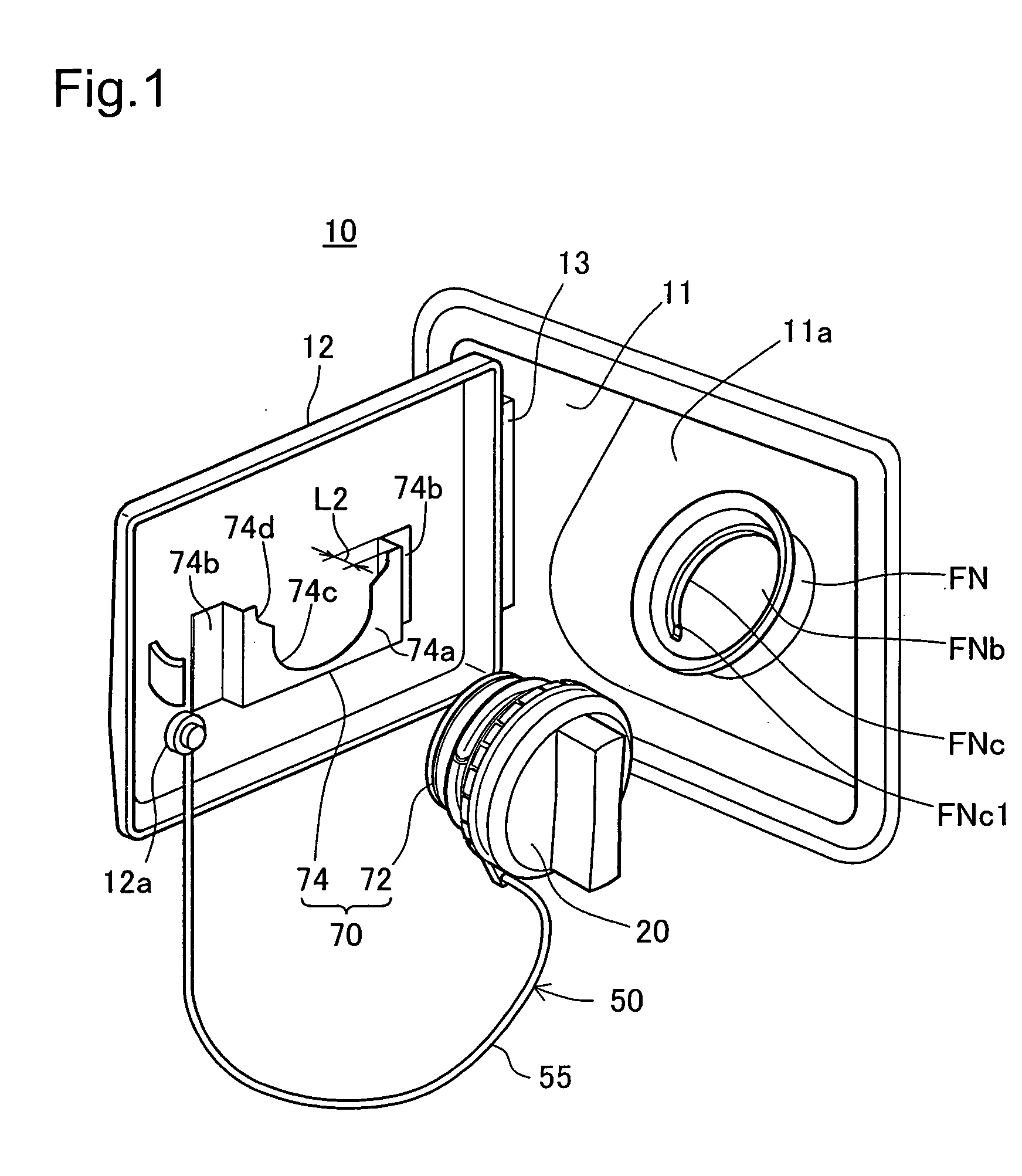
[0028]FIG. 1 is a perspective view showing a fuel cap 20 in a detached state after opening a fueling lid 12 on a rear side of a vehicle in one embodiment of the invention. An inlet box 11 for fuel supply is located in a rear portion of a body panel 10 and has its opening covered with the fueling lid 12. The fueling lid 12 is fastened to the inlet box 11 via a hinge 13 in a freely openable and closable manner. A fuel inlet FNb of a filler neck FN connecting with a fuel tank (not shown) is located in a bottom wall 11a of the inlet box 11. The fuel inlet FNb is opened and closed by the fuel cap 20.

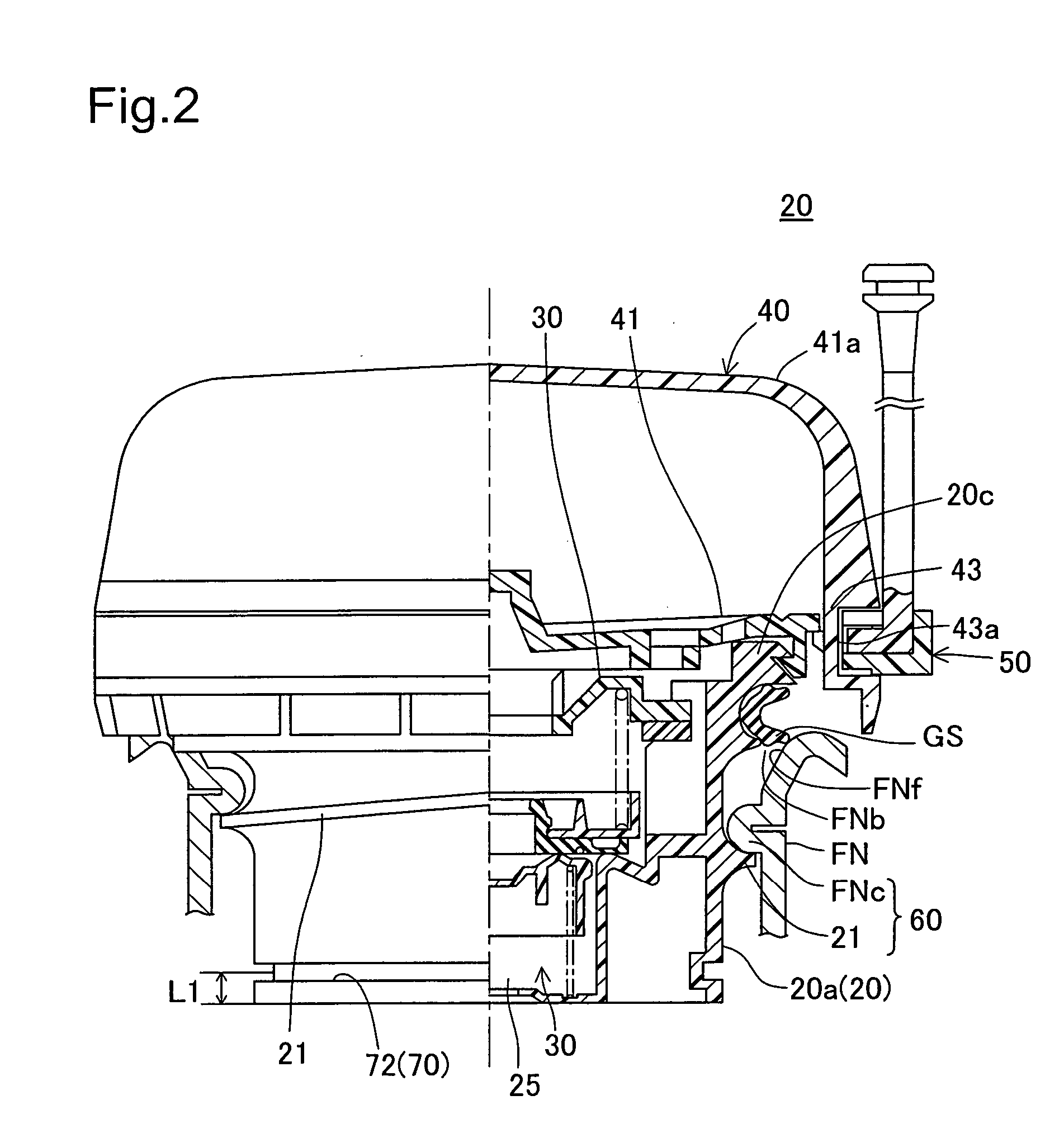
[0029]FIG. 2 is a half sectional view showing the fuel cap 20 attached to the filler neck FN. The fuel cap 20 includes a casing 20a fit in the filler neck FN, a pressure regulating valve 30 received in a valve chest 25 formed inside the casing 20a, a cover 40 that is mounted on the casing 20a and has a handle 41a that is manipulated with the thumb a...


PUM


Abstract

A cap device of the invention has a tether mechanism, which is used to link a fuel cap to a fueling lid. The tether mechanism includes a cord-like flexible linkage body having one end as a first support end, which is fit in a support member of a rotating ring. The first support end is inserted from inside of the rotating ring through an insertion opening into a support recess. This fits the first support end in the support recess, while allowing the linkage body to be led through a lead opening. The first support end is accordingly fixed to the support member. The rotating ring is then attached to a circular groove formed on the fuel cap. The tether mechanism of this simple structure is readily fixed and thereby ensures easy attachment to the fuel cap.

Description

[0001] This application claims the benefit of and priority from Japanese Applications No. 2003-336708 filed Sep. 29, 2003 and No. 2003-336712 filed Sep. 29, 2003, the contents of which are incorporated herein by reference. BACKGROUND OF THE INVENTION [0002] 1. Field of the Invention [0003] The present invention relates to a cap device equipped with a tether mechanism for linking a cap used to open and close a tank opening to a peripheral member of the tank opening. [0004] 2. Description of the Related Art [0005] In a fuel tank of automobiles, there is a known structure of linking a fuel cap to a peripheral member of a fuel inlet by means of a tether, in order to prevent the fuel cap from being lost during a fuel supply operation (see, for example, JP No. 2000-507192A). FIG. 8 shows a tether mechanism 100 of a prior art structure. The tether mechanism 100 includes a rotating ring 102 that is mounted in a freely rotatable manner on an outer circumference of a fuel cap (not shown), and...

Claims


Application Information

Patent Timeline
IPC IPC(8): B60K15/04B60K15/05B65D55/16E21D17/02
CPCY10S220/33B60K15/0406
Inventor HAGANO, HIROYUKINAKAGAWA, MASAYUKI
Owner TOYODA GOSEI CO LTD
Why Eureka
Try Eureka