Method of mounting condenser microphone on main PCB and condenser microphone adapted for the same

a technology of condenser microphone and main pcb, which is applied in the direction of mouthpiece/microphone attachment, printed circuit non-printed electric component association, final product manufacture, etc., can solve the problems of difficult mounting of main pcb and inability to use smt with elements with weak resistance to temperatur

Inactive Publication Date: 2005-05-05
BSE CO LTD
View PDF4 Cites 36 Cited by
  • Summary
  • Abstract
  • Description
  • Claims
  • Application Information

AI Technical Summary

Benefits of technology

[0010] An object of the present invention is to provide a method of mounting a condenser microphone on a main PCB and condenser microphone for the same, in which the condenser microphone has sound holes formed in a PCB of the condenser microphone instead of the casing of the condenser microphone, and is mounted on a main PCB, and the main PCB is provided with a through hole so that the condenser microphone can be freely mounted on the main PCB.

Problems solved by technology

Surface mount technology (SMT) may be used to miniaturize products, but the SMT cannot be used with elements having a weak resistance against temperature because a high temperature is applied to the parts during reflow of surface mount device (SMD).
However, in a conventional condenser microphone, it is difficult to mount a main PCB such that the front surface of the main PCB is directed toward an opposite direction of sound source, that is, such that the front surface is directed toward an inner space of a casing of the condenser microphone, because the casing has sound holes as shown in FIGS. 1A and 1B.

Method used


Image

  • Method of mounting condenser microphone on main PCB and condenser microphone adapted for the same
  • Method of mounting condenser microphone on main PCB and condenser microphone adapted for the same
  • Method of mounting condenser microphone on main PCB and condenser microphone adapted for the same

Examples


Embodiment Construction

[0024] Reference will now be made in detail to the preferred embodiments of the present invention, examples of which are illustrated in the accompanying drawings. Wherever possible, the same reference numbers will be used throughout the drawings to refer to the same or like parts.

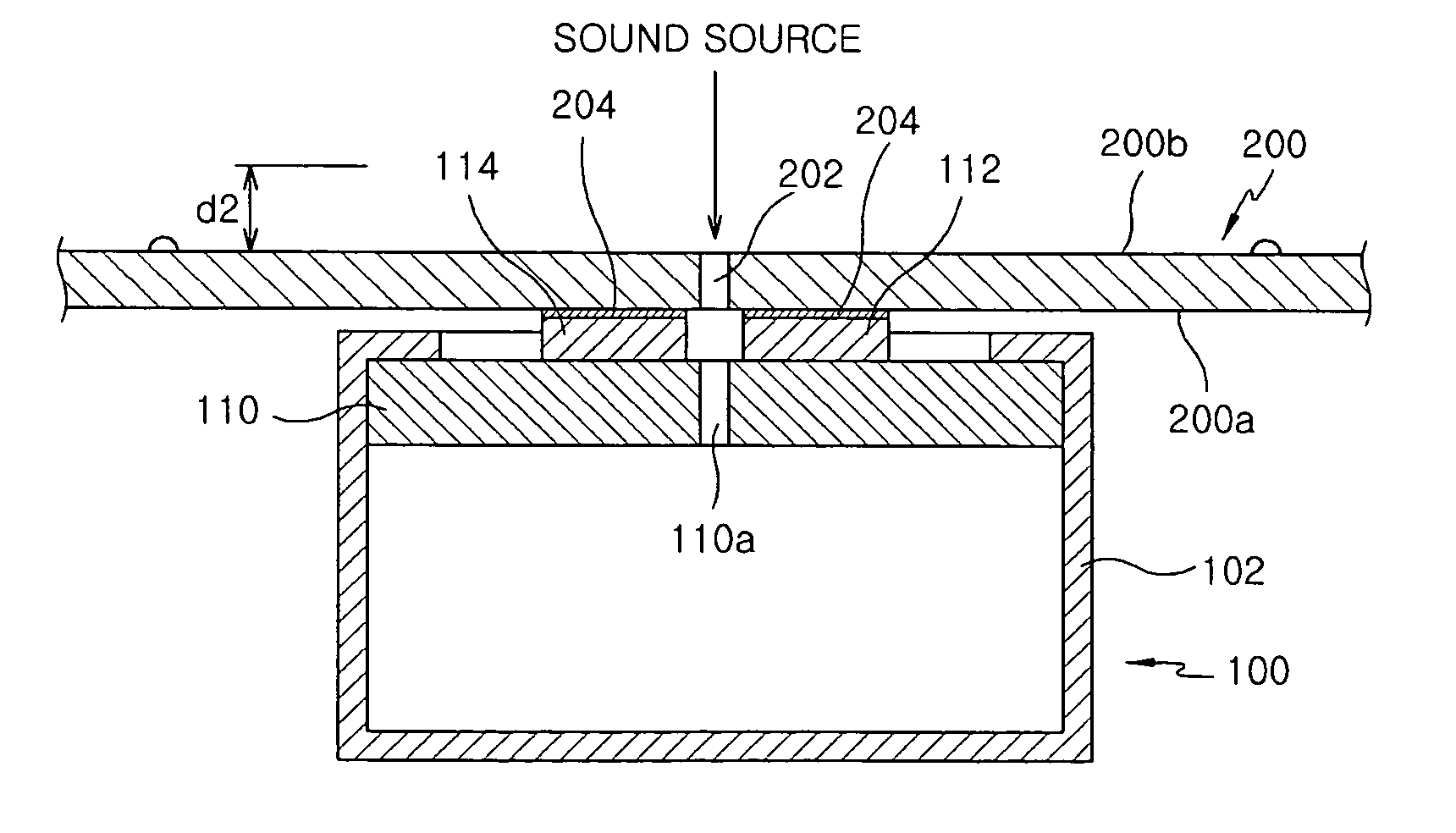
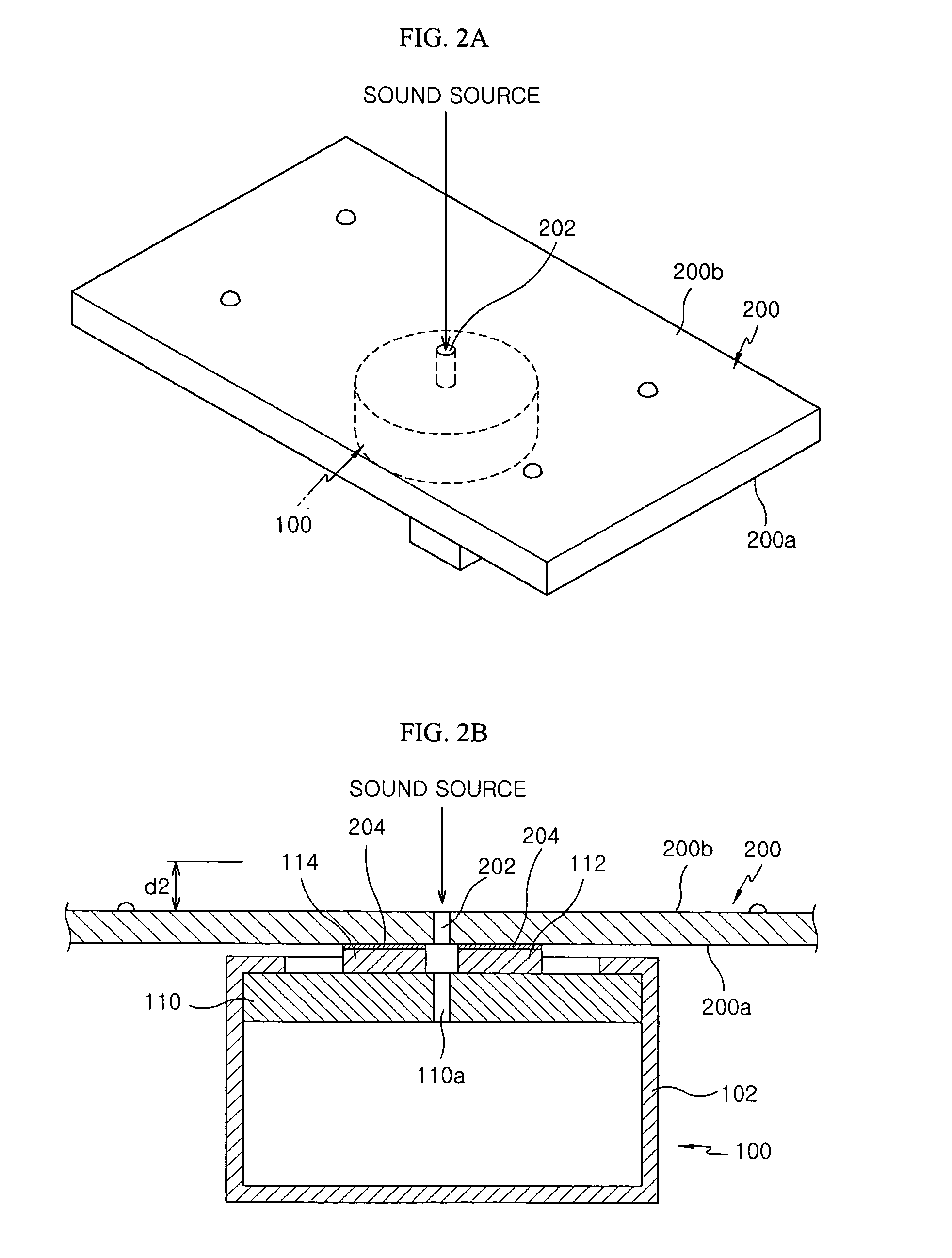
[0025]FIG. 2A is a perspective view of a condenser microphone mounted on a main PCB according to one illustrative embodiment of the present invention, and FIG. 2B is a side sectional view of a condenser microphone mounted on a main PCB according to this embodiment of the present invention.

[0026] Referring to FIGS. 2A and 2B, a condenser microphone 100 according to the present invention is mounted on an element mounting surface 200a of a main PCB 200 around a through hole 202 formed in the main PCB 200 by an ordinary soldering method or a SMD reflow such that sound waves are delivered via the through hole 202. According to the mounting method as described above, since the main PCB 200 can be mounted such t...


PUM


Abstract

A condenser microphone and a method of mounting a condenser microphone on a main PCB are provided. The method includes assembling the condenser microphone by assembling elements of the condenser microphone such that a vibration plate including a diaphragm and a backplate is directed toward an opened surface of a casing of the condenser microphone. The casing has a closed bottom surface and an opened surface opposite to the closed bottom surface. A PCB includes a sound hole. The assembled condenser microphone is positioned on a main PCB such that the sound hole of the PCB is aligned in accordance with a through hole formed in the main PCB. According to the present invention, if necessary, the main PCB can be mounted such that its elements surface is directed toward an inside of an electronic product, thereby maintaining good sound quality due to a short delivery path of sound waves.

Description

BACKGROUND OF THE INVENTION [0001] 1. Field of the Invention [0002] The present invention relates to a method of mounting a condenser microphone, and more particularly, to a method of mounting a condenser microphone on a main printed circuit board (PCB) and a condenser microphone adapted for the method. [0003] 2. Description of the Related Art [0004] Generally, customers desire high functionality and miniaturization of electronics products. Hence, manufacturers of electronic products are trying to make smaller products with to meet demand. Surface mount technology (SMT) may be used to miniaturize products, but the SMT cannot be used with elements having a weak resistance against temperature because a high temperature is applied to the parts during reflow of surface mount device (SMD). [0005] Additionally, assuming that SMT is used, it is necessary to direct a front surface of the main PCB, on which elements are mounted, toward an inward direction of an electronic product during the ...

Claims


Application Information

Patent Timeline
Patent Type & Authority Applications(United States)
IPC IPC(8): H04R1/06H04R1/08H04R19/00H04R19/01H04R19/04H05K1/18
CPCH04R1/06H04R1/083H05K2201/10083H05K1/181H05K2201/09072H04R19/00Y02P70/50H04R19/04
Inventor SONG, CHUNG DAMCHUNG, EEK JOOKIM, HYUN HO
Owner BSE CO LTD
Why Eureka
Try Eureka