Control of multiple peripherals

a technology of peripheral devices and control devices, applied in the direction of digital output to print units, instruments, digitally marking record carriers, etc., can solve the problems of exceedingly difficult to understand ui, and it is not possible to make settings for multiple peripherals

Inactive Publication Date: 2005-05-05
SEIKO EPSON CORP
View PDF12 Cites 17 Cited by
  • Summary
  • Abstract
  • Description
  • Claims
  • Application Information

AI Technical Summary

Benefits of technology

[0006] With the foregoing in view, it is an object of present invention to provide a technique for controlling multiple peripherals, whereby setting for a multitude of peripherals may be completed by means of a simple setting.
[0007] In order to achieve the aforementioned object according to the present invention, dependency relationship data and settable range data are stored in advance in a predetermined storage medium, and by referring to these sets of data, in the event that there is a working condition whose settable range varies in a manner dependent on a change in a certain working condition, the UI display takes place in such a way that the working condition is set, while accurately corresponding with variation in the settable range. Here, settable range data is stored for each individual peripheral working environment, and presents all settable ranges settable for a multiplicity of peripherals in the current working environment as decision branches, while eliminating duplication. When a change in a working condition setting made from the UI causes variation in the settable range for another working condition, reference is made to the settable range data, and a varying settable range is acquired.

Problems solved by technology

With a UI of the kind described above, if complex settings are being made, a complicated setting operation will be required of the user, making the UI difficult to understand, particularly for a novice user.
In situations such as one where several printing devices are connected to a computer, with multi-copy printing being distributed among these, making a series of settings in order to control multiple peripherals results in a UI that is exceedingly difficult to understand.
However, with conventional UIs, it was not possible to make settings for multiple peripherals, by means of a single UI setting.

Method used


Image

  • Control of multiple peripherals
  • Control of multiple peripherals
  • Control of multiple peripherals

Examples


Embodiment Construction

[0051] The following description of the embodiments of the invention will be made according to the order indicated below. [0052] (1) Arrangement of the Invention: [0053] (1-1) Arrangement of UI Control Module: [0054] (2) Arrangement of Standard Print Data: [0055] (3) Arrangement of Printer DB: [0056] (4) Arrangement of Resource DB: [0057] (5) Print Control Process and UI Display Example: [0058] (6) Other Embodiments

[0059] (1) Arrangement of the Invention:

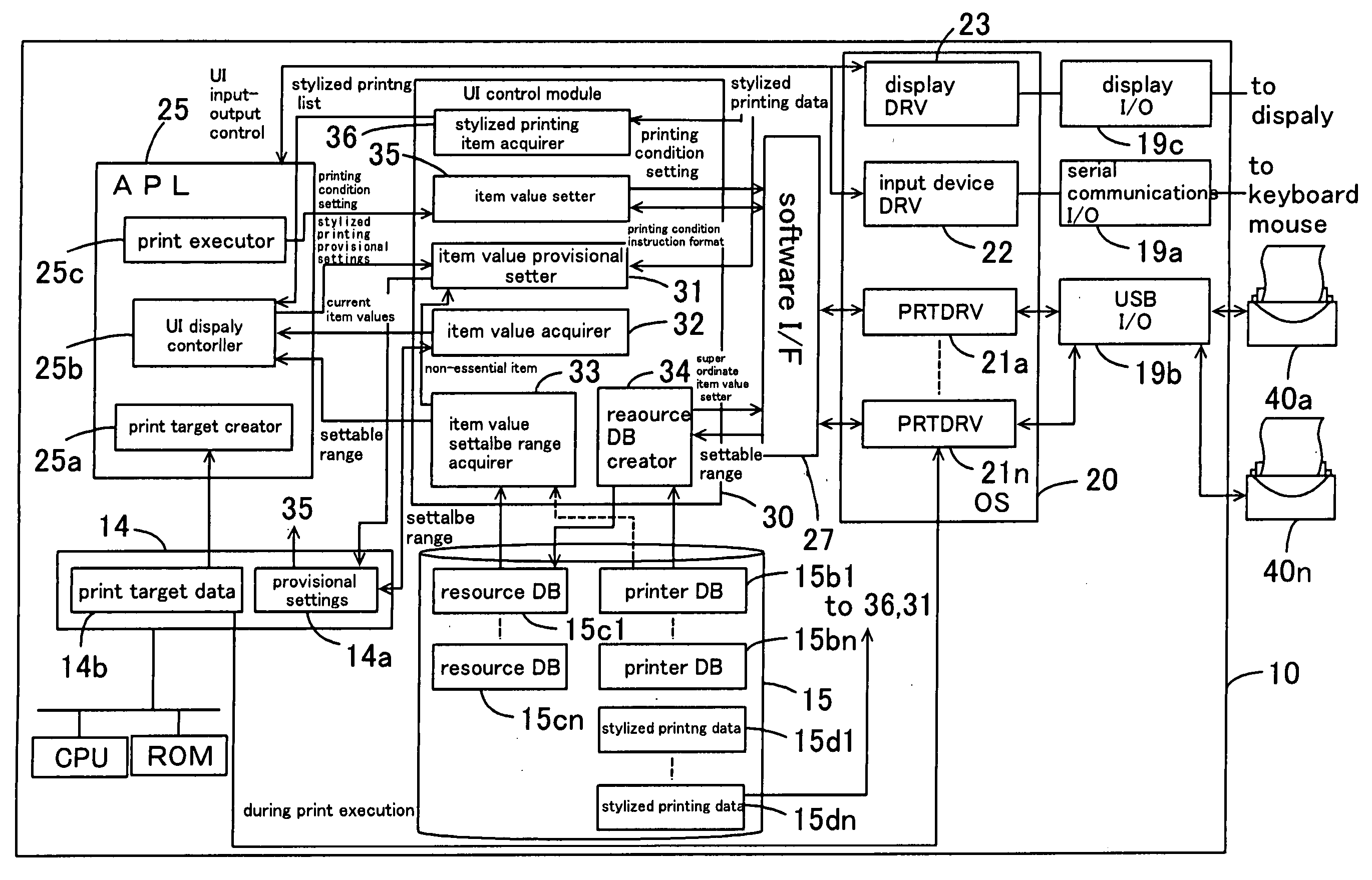
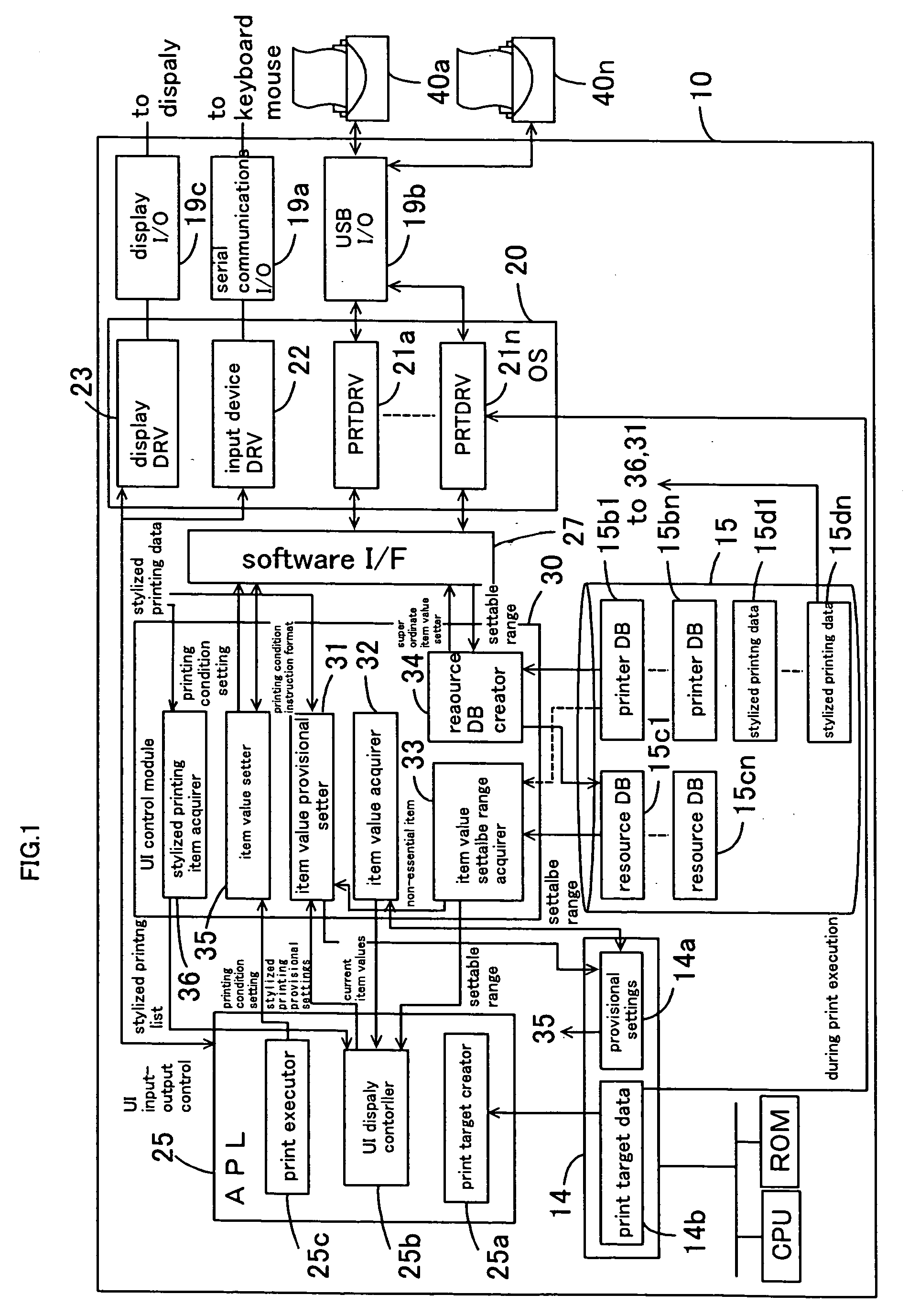
[0060]FIG. 1 is a block diagram showing a simplified arrangement of a computer as a print control device pertaining to the invention. Computer 10 comprises a CPU which serves as the center for operations, ROM and RAM 14 as storage media, and the like; [the computer] is able to execute a predetermined program while utilizing peripherals such as an HDD 15. Operating input devices such as a keyboard and mouse are connected to the computer 10 via a serial communications I / O 19a, and a display for image display is connected via a displ...


PUM


Abstract

When setting by means of a UI working conditions for a multiplicity of peripherals connected to a computer to control working of said peripherals, working environment data that identifies the working environment of the peripherals and dependency relationship data that indicates dependency relationships among said working conditions are stored in advance in a predetermined storage medium, the settable range data is referred to in order to acquire settable ranges for working conditions of the multiplicity of peripherals, settable ranges within which said multiplicity of peripherals are settable in the current working environment are all made decision branches without duplication, and peripherals are driven with settings made on the basis of this display.

Description

BACKGROUND OF THE INVENTION [0001] 1. Field of the Invention [0002] The present invention relates to working condition settings and control of peripheral devices. [0003] 2. Description of the Related Art [0004] Ordinarily, a control program referred to as a driver is utilized to drive a printing device or other computer peripheral. In a driver, working condition settings for driving a peripheral are received, and the peripheral is driven in accordance with these settings. Typically, a UI (User Interface) is displayed on a display or the like, and working condition settings are made by the user through this UI. [0005] With a UI of the kind described above, if complex settings are being made, a complicated setting operation will be required of the user, making the UI difficult to understand, particularly for a novice user. In situations such as one where several printing devices are connected to a computer, with multi-copy printing being distributed among these, making a series of set...

Claims


Application Information

Patent Timeline
Patent Type & Authority Applications(United States)
IPC IPC(8): G06F3/00G06F13/10G06F3/12
CPCG06F3/1204G06F3/1255G06F3/1232G06F3/1208
Inventor SAITO, MASANORITAKENUKI, JYUNICHIKANAYAMA, HIRAKU
Owner SEIKO EPSON CORP
Why Eureka
Try Eureka