
Drum type washing machine

Inactive Publication Date: 2005-05-12
SAMSUNG ELECTRONICS CO LTD
View PDF5 Cites 46 Cited by
  • Summary
  • Abstract
  • Description
  • Claims
  • Application Information

AI Technical Summary

Benefits of technology

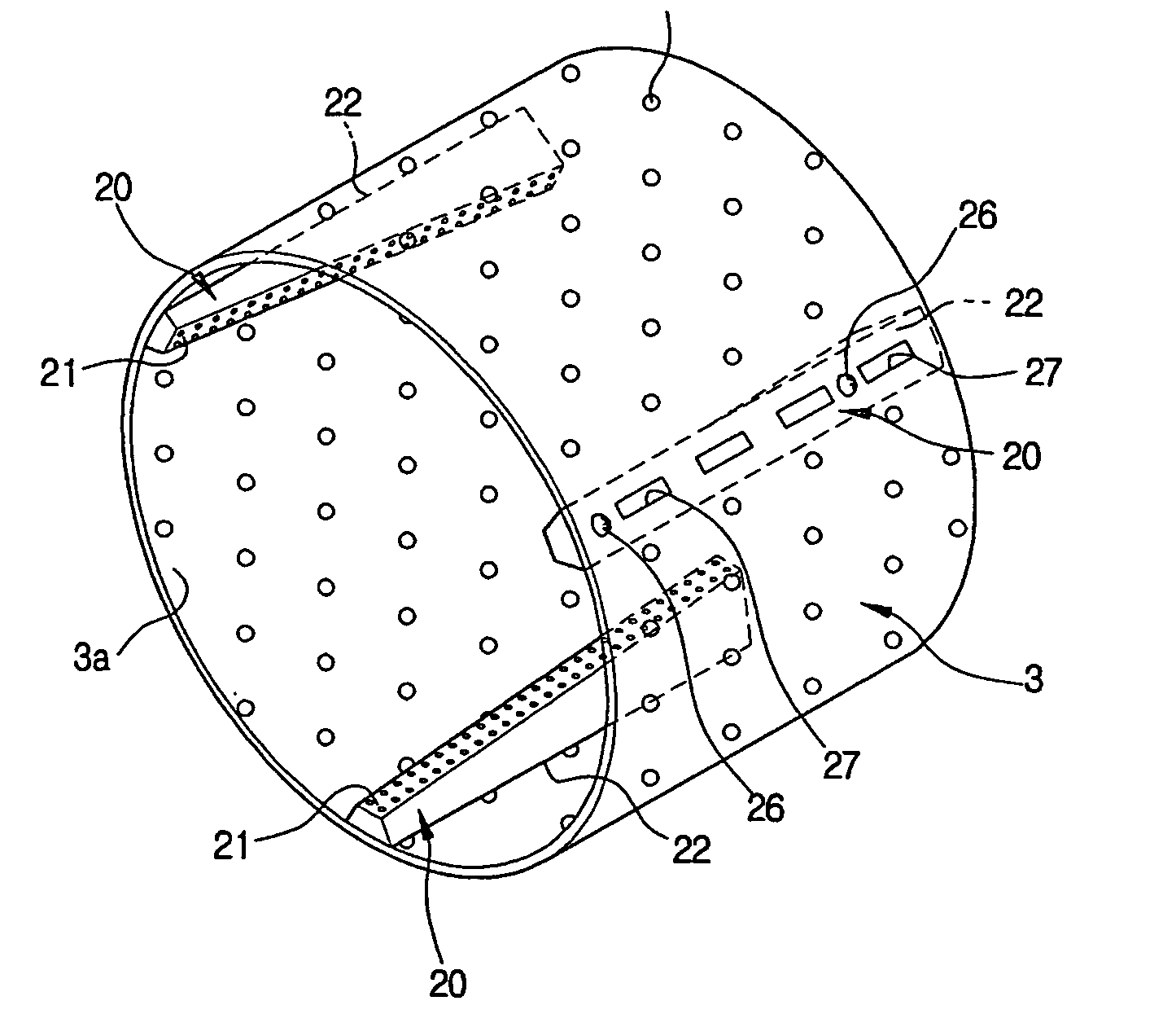
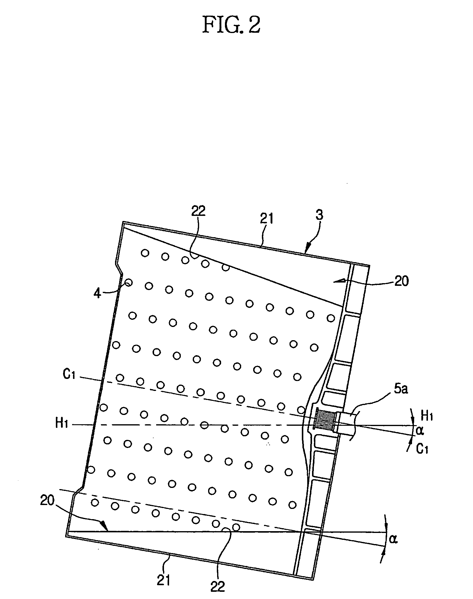
[0016] The present invention has been made in view of the problems involved with the above mentioned conventional drum type washing machines, and an aspect of the invention is to provide a drum type washing machine in which axially-extending lifters arranged around an inner peripheral surface of a rotating tub which is upwardly inclined have an improved structure, thereby achieving an improvement in wash performance.

Problems solved by technology

For this reason, there is inconvenience.
When the rotating tub rotates in such a state, the laundry positioned at a level higher than the height of the lifters at the rear end portion of the rotating tub may not be lifted by the lifters, so that it is ineffectively washed.
On the other hand, the amount of laundry lifted by the lifters at the front end portion of the rotating tub is relatively small.
As a result, the lifters operate inefficiently.
Furthermore, the laundry not lifted by the lifters at the rear end portion of the rotating tub may be entangled as the lifters are rotated along with the rotating tub.
As a result, the laundry may be damaged.
There is also inconvenience in that the user must disentangle the entangled laundry after completion of the washing process.
As a result, the laundry tends to bunch up at the rear end portion of the rotating tub even more.
When the laundry is mainly positioned at the rear end portion of the rotating tub, dynamic unbalance also occurs because a relatively large load is applied to the rear end portion of the rotating tub, whereas a relatively small load is applied to the front end portion of the rotating tub.
As a result, the rotating operation of the rotating tub is inefficiently carried out.
However, the amount of wash water sprayed through the water spray holes is small.
As a result, the laundry positioned at the front end portion of the rotating tub is insufficiently doused with the wash water, so that the laundry is ineffectively washed.

Method used


Image

  • Drum type washing machine
  • Drum type washing machine
  • Drum type washing machine

Examples


Embodiment Construction

[0040] Reference will now be made in detail to the embodiments of the present invention, examples of which are illustrated in the accompanying drawings, wherein like reference numerals refer to the like elements throughout. The embodiments are described below to explain the present invention by referring to the figures.

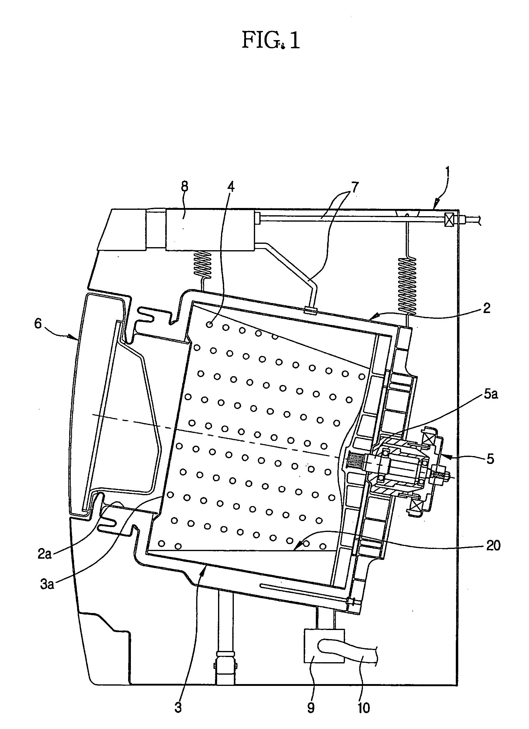
[0041]FIG. 1 is a sectional view schematically illustrating the configuration of a drum type washing machine according to the present invention. As shown in FIG. 1, the drum type washing machine according to the present invention includes a housing 1 having an approximately box shape to define an outer appearance of the washing machine, a drum-shaped water tub 2 installed in the housing 1 and adapted to contain wash water, a drum-shaped rotating tub 3 rotatably positioned in the water tub 2 and including spin-dry holes 4 at a peripheral wall of the rotating tub, and a drive motor 5 adapted to rotate the rotating tub 3, in order to wash and spin-dry laundry contained ...


PUM


Abstract

A drum type washing machine has axially-extending lifters arranged around an inner peripheral surface of a rotating tub which is upwardly inclined to allow easy laundry loading and unloading. The lifters each have a height gradually reducing to correspond to the inclination angle of the rotating tub from a rear end of the rotating tub to a front end thereof. Each lifter has, at its top portion, a wave-shaped structure including crests and valleys alternately arranged at a certain pitch. Each of the crests and valleys has water spray holes. The lifter includes at least one partition plate which divides the interior of the lifter into at least two chambers. Accordingly, wash water raised by each lifter is uniformly sprayed throughout the length of the lifter.

Description

CROSS-REFERENCE TO RELATED APPLICATIONS [0001] This application claims the benefit of Korean Application No. 2003-79248, Korean Application No. 2003-79250, and Korean Application No. 2003-79252, each filed Nov. 10, 2003 in the Korean Intellectual Property Office, the entire disclosures of which are incorporated herein by reference. BACKGROUND OF THE INVENTION [0002] 1. Field of the Invention [0003] The present invention relates to a drum type washing machine, and more particularly, to a drum type washing machine in which axially-extending lifters arranged around an inner peripheral surface of a rotating tub upwardly inclinedly installed to allow easy laundry loading and unloading operations have an improved structure, thereby being capable of achieving an improvement in wash performance. [0004] 2. Description of the Related Art [0005] A conventional washing machine generally includes a housing forming an outer appearance of the washing machine, a cylindrical water tub installed in t...

Claims


Application Information

Patent Timeline
IPC IPC(8): D06F23/02D06F23/06D06F37/04D06F37/06D06F39/12
CPCD06F23/06D06F37/065D06F37/04
Inventor KIM, HYUN SOOKNAMKUNG, KOAN SEOGROH, HYOUNG HOON
Owner SAMSUNG ELECTRONICS CO LTD
Learn More