Vanity cabinet with drawers

Inactive Publication Date: 2005-05-12
LOWE MARK JEFFREY
View PDF16 Cites 34 Cited by
  • Summary
  • Abstract
  • Description
  • Claims
  • Application Information

AI Technical Summary

Benefits of technology

[0017] It is an object of the present invention to provi

Problems solved by technology

This persisted even with the deficits of having hot and cold water supplies and drain plumbing enclosed within fine cabinetry.
While this type of device may be suitable for use in a vanity cabinet, it has not come to the attention of t

Method used


Image

  • Vanity cabinet with drawers
  • Vanity cabinet with drawers
  • Vanity cabinet with drawers

Examples


Example

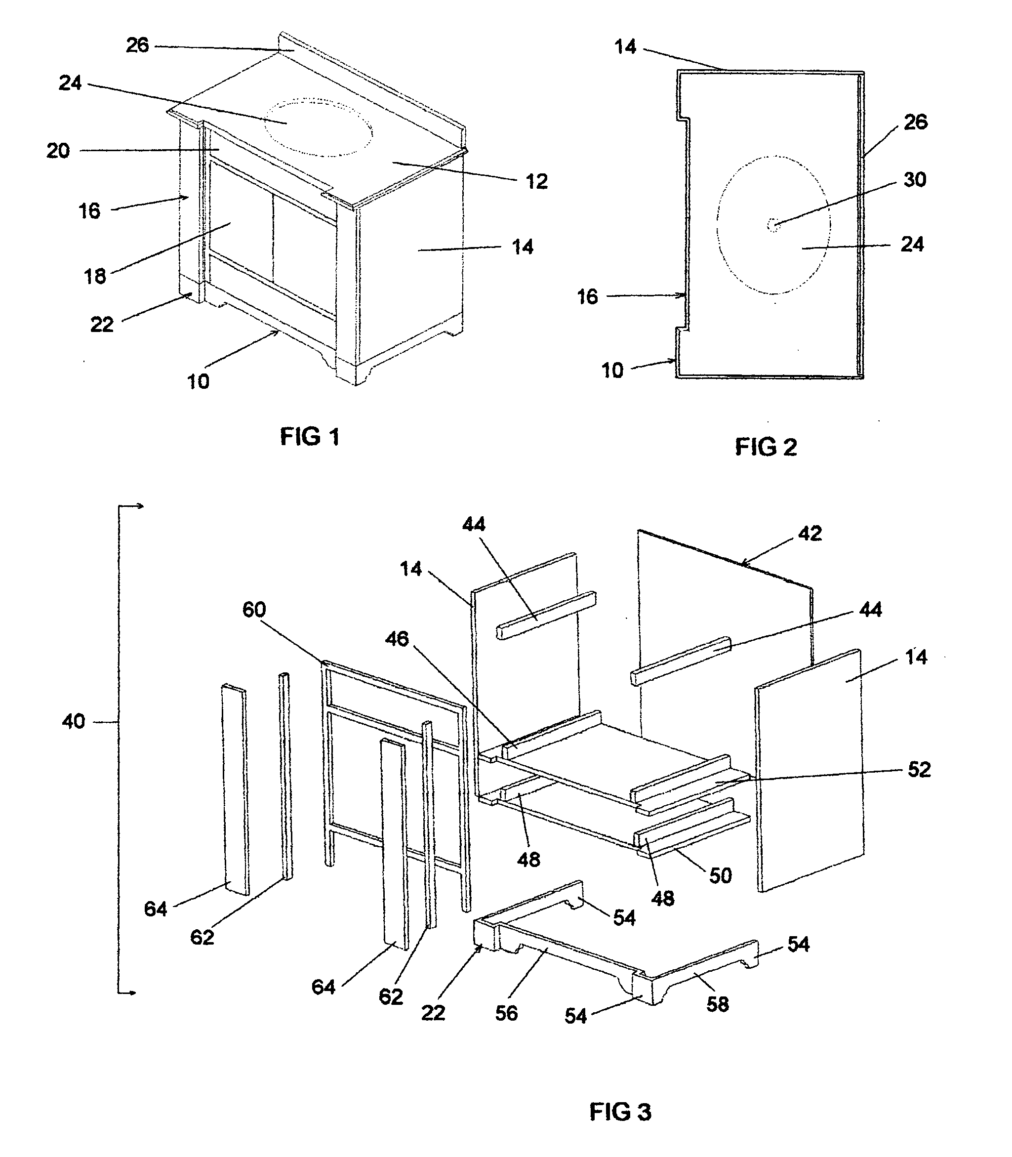
[0039] A vanity cabinet 10 in accordance with the present invention is shown in FIG. 1 with a top 12, sidewalls 14, front 16, doors 18, top drawer 20, base 22, lavatory 24 and backsplash 26. Further, in FIG. 2, the vanity cabinet includes a lavatory with a drain 30.

[0040] As shown in FIG. 3, a carcass for a vanity cabinet is comprised of generally a cabinet body 40, with cabinet back 42, top drawer stringers 44, middle drawer stringers 46, and bottom drawer stringers 48. Also included are the cabinet bottom 50, middle stringer bottom 52 which are both located interior to the carcass as a whole.

[0041] Other components of the cabinet body 40 are the cabinet feet 54, the toe rail 56, the side rails 58, the face frame 60, the molding 62 and the front fascia 64.

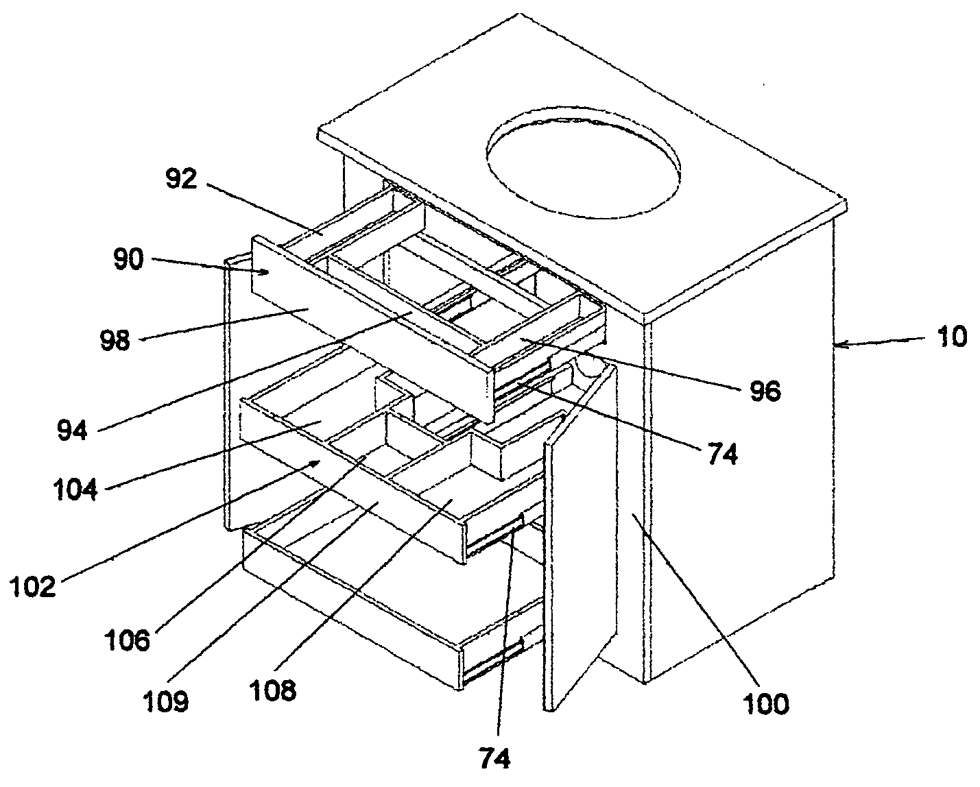
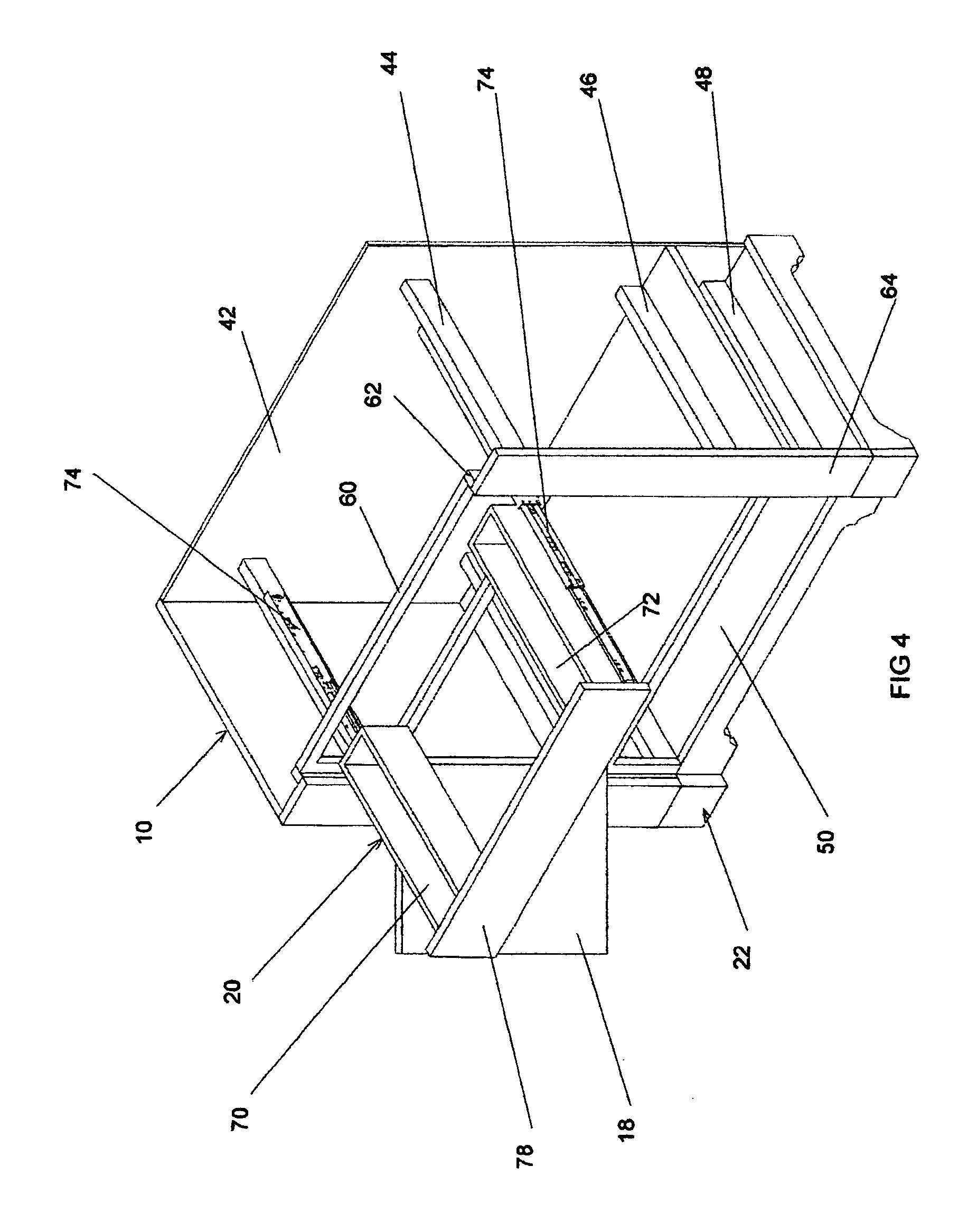
[0042] Turning now to FIG. 4, a portion of the vanity cabinet 10 is shown with a drawer of the present invention. The vanity cabinet is shown partially for purposes of clarity. In this instance, the top drawer 20 is shown in th...


PUM


Abstract

A new vanity cabinet with a functional lavatory included therein is disclosed with modified drawers that compatibly circumvent the portions of the lavatory basin and the associated plumbing service to same, when the drawers are opened and closed. The vanity cabinet of the present invention therefore provides for increased storage and utility.

Description

CROSS REFERENCE TO RELATED APPLICATIONS [0001] Not applicable. STATEMENT REGARDING FEDERALLY SPONSORED RESEARCH OR DEVELOPMENT [0002] Not applicable. BACKGROUND OF THE INVENTION [0003] The present invention relates to vanity cabinets, e.g., wooden cabinets fitted with lavatories or basins and associated plumbing. More specifically, the present invention relates to vanity cabinets that are constructed using modern manufacturing techniques and materials. [0004] Vanities originally arose from a need to have a modest sink in the vicinity of a dressing room in hotels or in upscale residences. It may well be that the first vanities were nothing more than a cabinet structure with a recessed bowl or basin where the user could stand or sit and access the basin as needed. This progressed with the development of indoor plumbing to the point that the vanity was supplied with running water and a drain system. [0005] Some vanities were merely countertops with a skirted front area, where space und...

Claims


Application Information

Patent Timeline
IPC IPC(8): A47B67/04A47B77/06A47K1/02E03C1/32
CPCA47B67/04A47B77/06E03C2001/321A47K1/02E03C1/32A47B2220/03
Inventor LOWE, MARK JEFFREY
Owner LOWE MARK JEFFREY
Why Eureka
Try Eureka