Drive circuit for illumination unit

a technology of driving circuit and illumination unit, which is applied in the direction of instruments, light sources, inductances, etc., can solve the problem of luminance dispersion between lamps

Inactive Publication Date: 2005-05-12
KOHNO KAZUO
View PDF8 Cites 85 Cited by
  • Summary
  • Abstract
  • Description
  • Claims
  • Application Information

AI Technical Summary

Benefits of technology

[0028]FIG. 17 denotes a circuit dia

Problems solved by technology

Furthermore, in case of driving a plurality of the lamps, a system of connecting the electrode of the one lamp to the high tension terminal at the secondary side of the output transformer and driving the lamp by connecting the other electrode to the earth is generally employed, but this system has drawbacks such as causing a potential differe

Method used


Image

  • Drive circuit for illumination unit
  • Drive circuit for illumination unit
  • Drive circuit for illumination unit

Examples


Embodiment Construction

[0029] The mode of embodiment of the present invention will be described in the following by referring to attached drawings.

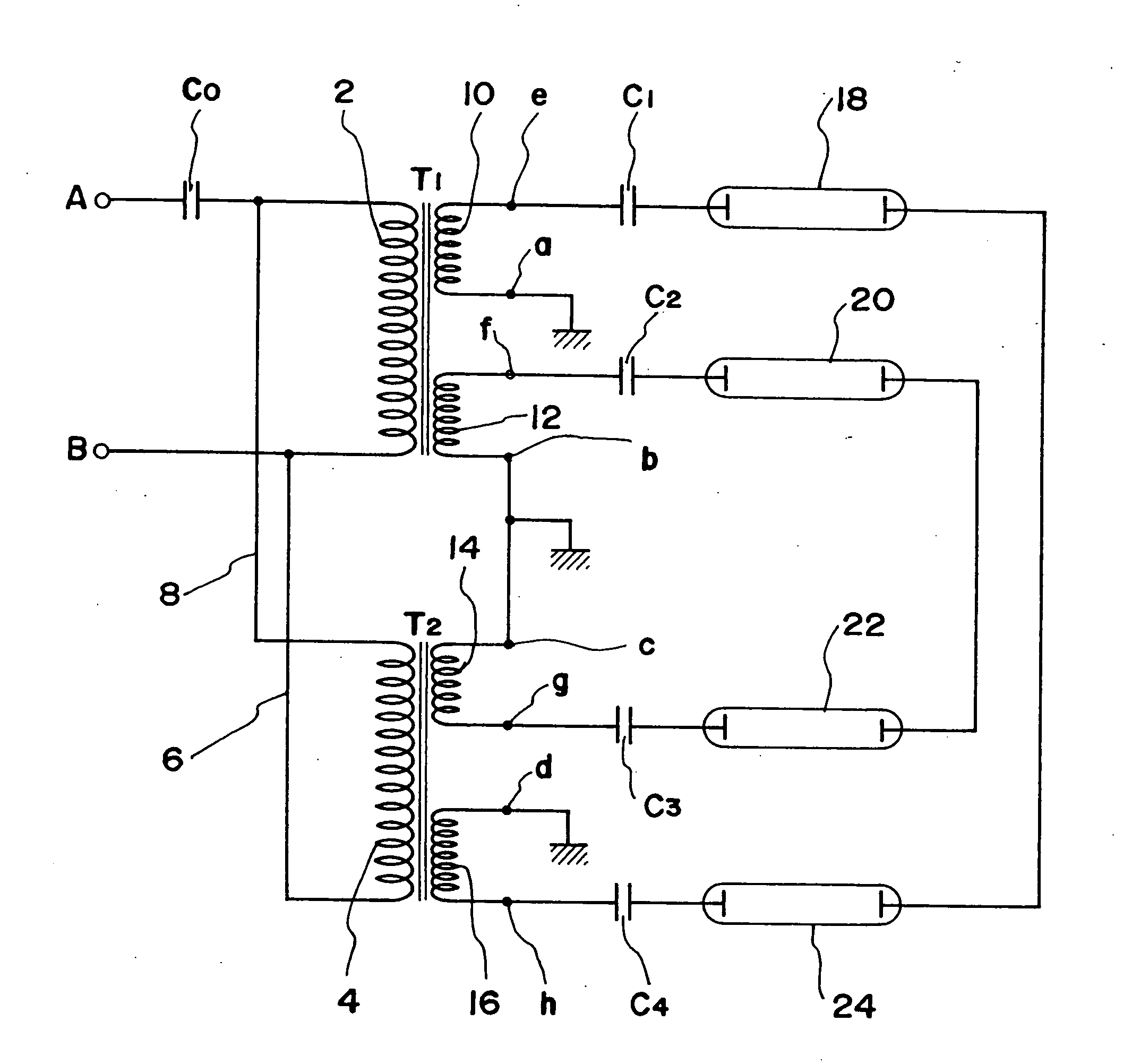
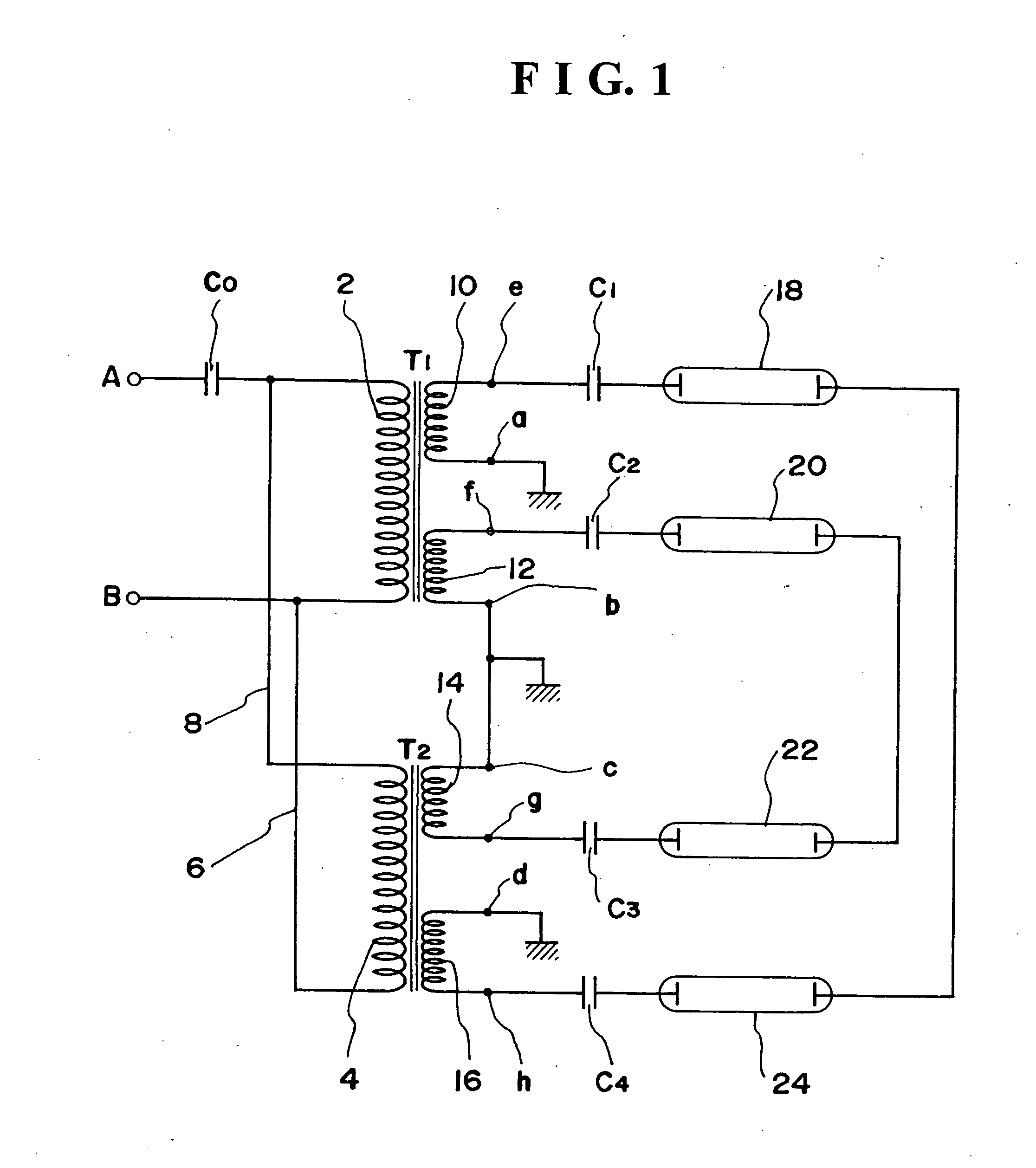
[0030] In FIG. 1, T1 and T2 denote output transformer for high tension of identical structure and identical standard wherein one input.2 outputs of wound type are provided, and input windings 2 and 4 at primary side are connected in parallel by lead wires 6 and 8. A series resonance circuit is formed by a resonance capacitor Co and L of a primary winding 2 between input terminals A and B of the output transformer T1. The input terminals A and B are connected to an inverter circuit, and AC voltage to be outputted from the inverter circuit is inputted to the input terminals A and B. Each terminal a, b, c, d of secondary windings 10, 12, 14, 16 of each output transformer T1 and T2 are connected to the earth by means of the terminals.

[0031] Reference numerals 18 and 24 denote cold cathode fluorescent lamps, and the lamps are connected serially to each other. An e...


PUM


Abstract

In case of driving a plurality of lamps with the use of a plurality of output transformers, difference in the brightness of each lamp occurs by a dispersion of characteristics of the output transformers, and an object of this invention is to prevent such troubles. For this purpose, primary side of a plurality of output transformers of 1 input.plural output type are respectively connected, and illumination units are connected to the secondary side of each output transformer. All of the secondary output terminals of each output transformer are connected to the secondary output terminals of counter phase are connected by forming a loop circuit with the connection of the output terminals in series in closed loom form and the illumination units are connected between the secondary output terminals of the output transformer and the output terminal of the other output transformer of counter phase with the output terminal.

Description

BACKGROUND OF THE INVENTION [0001] The present invention relates to a drive circuit used for inverters or the like that drive an illumination unit such as cold cathode fluorescent lamp or EL display (electroluminescence display) and the like. [0002] Heretofore, ballastless type discharge lamp drive circuit using multilamp leakage transformer as a circuit for driving a plurality of discharge lamps has been known (for example, refer to official gazette of Japan Tokkai 2002-075756). Furthermore, a discharge lamp drive circuit has been developed which drives by connecting primary sides of a plurality of output transformers in parallel and connecting the discharge lamps to the secondary sides of each output transformer. [0003] Furthermore, heretofore, in case where an illumination unit such as a plurality of cold cathode fluorescent lamps is driven by using a high tension terminal at secondary side of the wound transformer of one input.2 outputs, as shown in FIG. 17, primary sides of eac...

Claims


Application Information

Patent Timeline
IPC IPC(8): H05B41/14H05B41/231H05B41/282
CPCH05B41/2822H01F38/10H05B41/14H05B41/26H05B41/231
Inventor KOHNO, KAZUO
Owner KOHNO KAZUO
Why Eureka
Try Eureka