Battery charging circuit and charging method

a charging circuit and battery technology, applied in battery/fuel cell control arrangement, dynamo-electric converter control, instruments, etc., can solve the problems of a large number of charger components, insufficient charging or overcharging, and complicated charger configuration

Active Publication Date: 2011-09-08
TOYOTA IND CORP
View PDF8 Cites 24 Cited by
  • Summary
  • Abstract
  • Description
  • Claims
  • Application Information

AI Technical Summary

Benefits of technology

[0007]Accordingly, it is an objective of the present invention to provide a battery charging circuit and a charging method that allows constant current charging to be perform

Problems solved by technology

Thus, insufficient charging or overcharging can occur.
However, the method requires a great number of

Method used


Image

  • Battery charging circuit and charging method
  • Battery charging circuit and charging method
  • Battery charging circuit and charging method

Examples


first embodiment

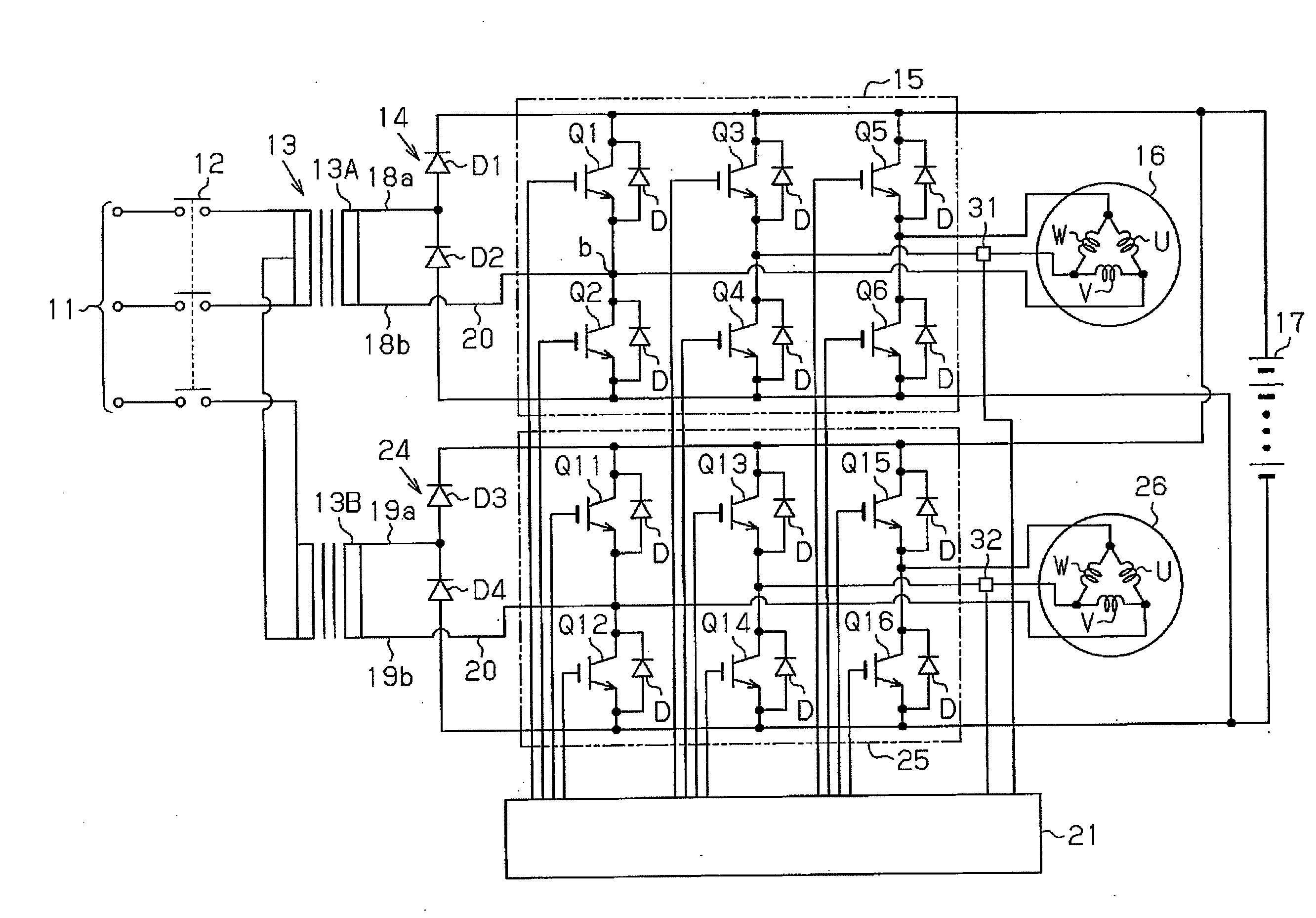
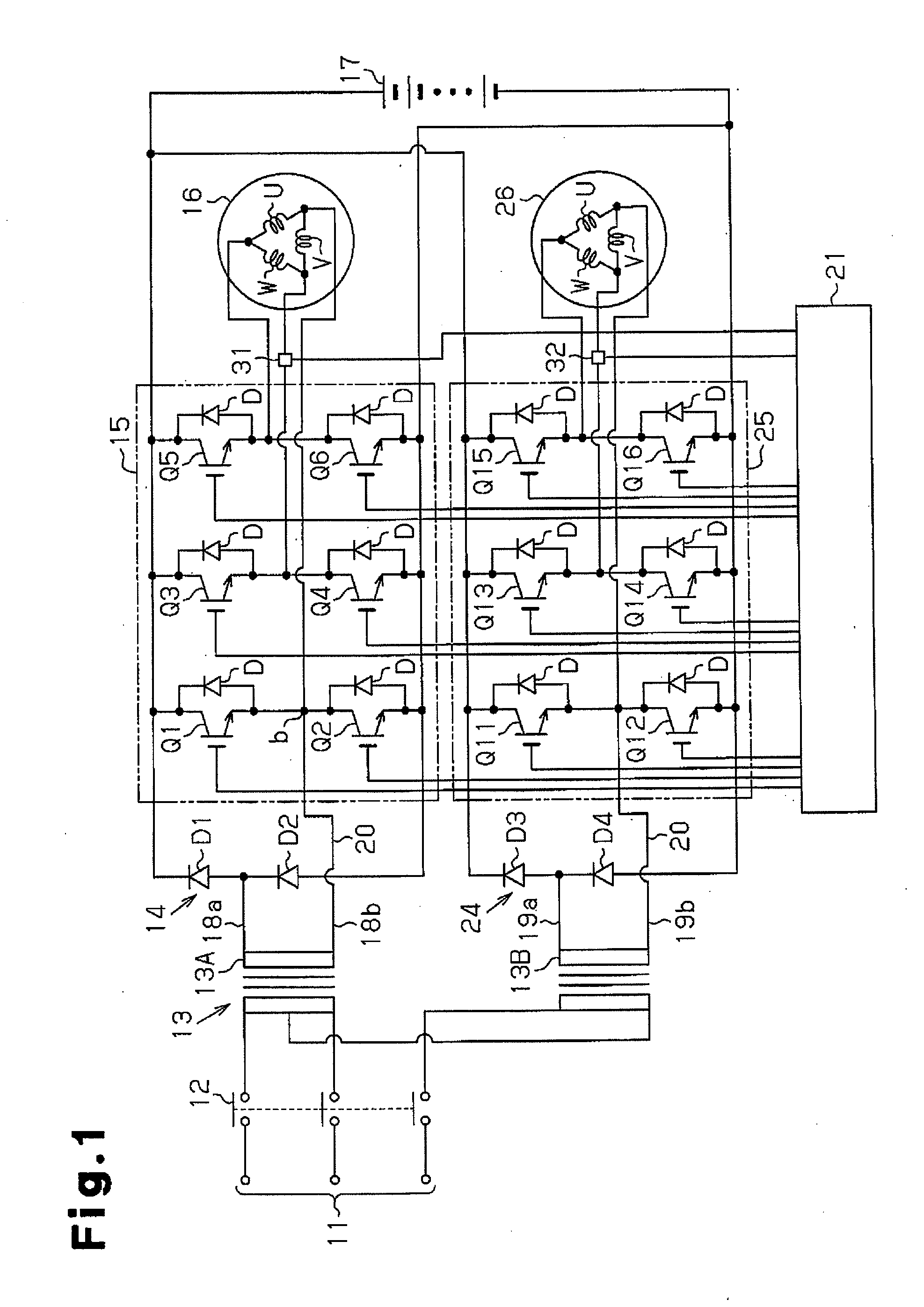
[0025]A battery forklift according to a first embodiment of the present invention will now be described with reference to FIGS. 1 to 6. The motor drive system of the battery forklift includes inverters, and a vehicle-driving motor and a cargo-handling motor, which receive power from a battery and are controlled by the inverters. Coils of the vehicle-driving motor and the cargo-handling motor and switching elements of the inverters are used to form a battery charging circuit. In other words, the battery charging circuit is formed by externally attaching additional parts to the inverters of the motor drive system.

[0026]As shown in FIG. 1, the battery charging circuit includes a Scott connection transformer, which is a single-phase output transformer connected to a three-phase alternating-current power source 11 (for example, a commercial power source such as a 200 V alternating-current power source) via a switch 12. “The single-phase output transformer” refers to a transformer that ha...

second embodiment

[0056]A second embodiment will now be described with reference to FIGS. 7 to 9. The present embodiment is different from the first embodiment in that a circuit used for charging is used to convert the power of a battery to an alternating-current power to be supplied to the primary side of a Scott connection transformer. Like or the same reference numerals are given to those components that are like or the same as the corresponding components of the first embodiment, and the explanations thereof are omitted.

[0057]As shown in FIG. 7, a first rectifier circuit 14 is connected to a vehicle-driving inverter 15. The first rectifier circuit 14 is formed by diodes D1, D2. Transistors Tr1, Tr2 serving as switching elements are connected in parallel with the diodes D1, D2, respectively. A second rectifier circuit 24 is connected to a cargo-handling inverter 25. The second rectifier circuit 24 is formed by diodes D3, D4. Transistors Tr1, Tr4 serving as switching elements are connected in paral...


PUM


Abstract

A charging circuit is provided that charges a battery for supplying power to a motor drive system that includes a three-phase motor and a three-phase inverter for controlling the three-phase motor. The three-phase inverter includes first to third sets of switching elements. Each set corresponds to one of the three phases. The charging circuit includes a single-phase output transformer, a rectifier circuit, a line, and a controller. The single-phase output transformer includes a secondary side output section having a first terminal and a second terminal. The rectifier circuit is connected in parallel with the three-phase inverter and the battery. The rectifier circuit is also connected to the first terminal of the secondary side output section. The line connects a connecting point between the first set of the switching elements in the three-phase inverter with the second terminal of the secondary side output section. The controller performs on-off control of the first to third sets of the switching elements. During charging of the battery, the controller maintains the first set of the switching elements in an OFF state, and performs the on-off control of at least one set of the second and third sets of the switching elements.

Description

BACKGROUND OF THE INVENTION[0001]The present invention relates to a battery charging circuit, and more particularly, to a battery charging circuit and charging method suitable for charging a battery that supplies power to a motor drive system having a motor such as a vehicle-driving motor and a three-phase inverter for driving the motor, for example, a motor drive system in an electric vehicle or a hybrid vehicle.[0002]A large-sized battery mounted as a power source on a vehicle such as an electric vehicle needs to be charged when the amount of charge is less than or equal to a predetermined amount.[0003]Conventionally, a liquid type lead-acid battery is charged via a quasi-constant voltage transformer and a rectifier circuit. In this charging method, the charging current is greater when the battery voltage is low. As the battery voltage increases, the charging current is reduced.[0004]In the charging method using a quasi-constant voltage transformer, the charging performance depend...

Claims


Application Information

Patent Timeline
IPC IPC(8): H02J7/02H02J7/00
CPCB60L11/1811Y02T10/7005Y02T90/14Y02T10/7016Y02T90/127Y02T10/7011Y02T10/7072B60L1/006B60L2200/42B60L2210/30B60L2210/40Y04S10/126Y02P90/60B60L53/14B60L53/22B60L53/20B60L53/24B60L55/00B60L58/15H02J2310/48H02J7/02H02J2207/20Y02E60/00Y02T10/70Y02T10/72H02M1/0085Y02T10/92H02J7/00Y02T90/12Y02T90/16
Inventor FUKATSU, TOSHINARI
Owner TOYOTA IND CORP
Why Eureka
Try Eureka