Wearable light device with optical sensor

a technology of optical sensors and light devices, applied in the field of wearable light devices, to achieve the effect of enhancing vision

Inactive Publication Date: 2005-05-12
FOXFURY
View PDF14 Cites 84 Cited by
  • Summary
  • Abstract
  • Description
  • Claims
  • Application Information

AI Technical Summary

Benefits of technology

[0009] The invention is a wearable light device to enhance vision at night and in low-light areas. The wearable light device includes a wearable mount for attaching the device to a par

Problems solved by technology

Dimming the LEDs when their light is not needed conserves the battery or other power source, making it unn

Method used


Image

  • Wearable light device with optical sensor
  • Wearable light device with optical sensor
  • Wearable light device with optical sensor

Examples


Embodiment Construction

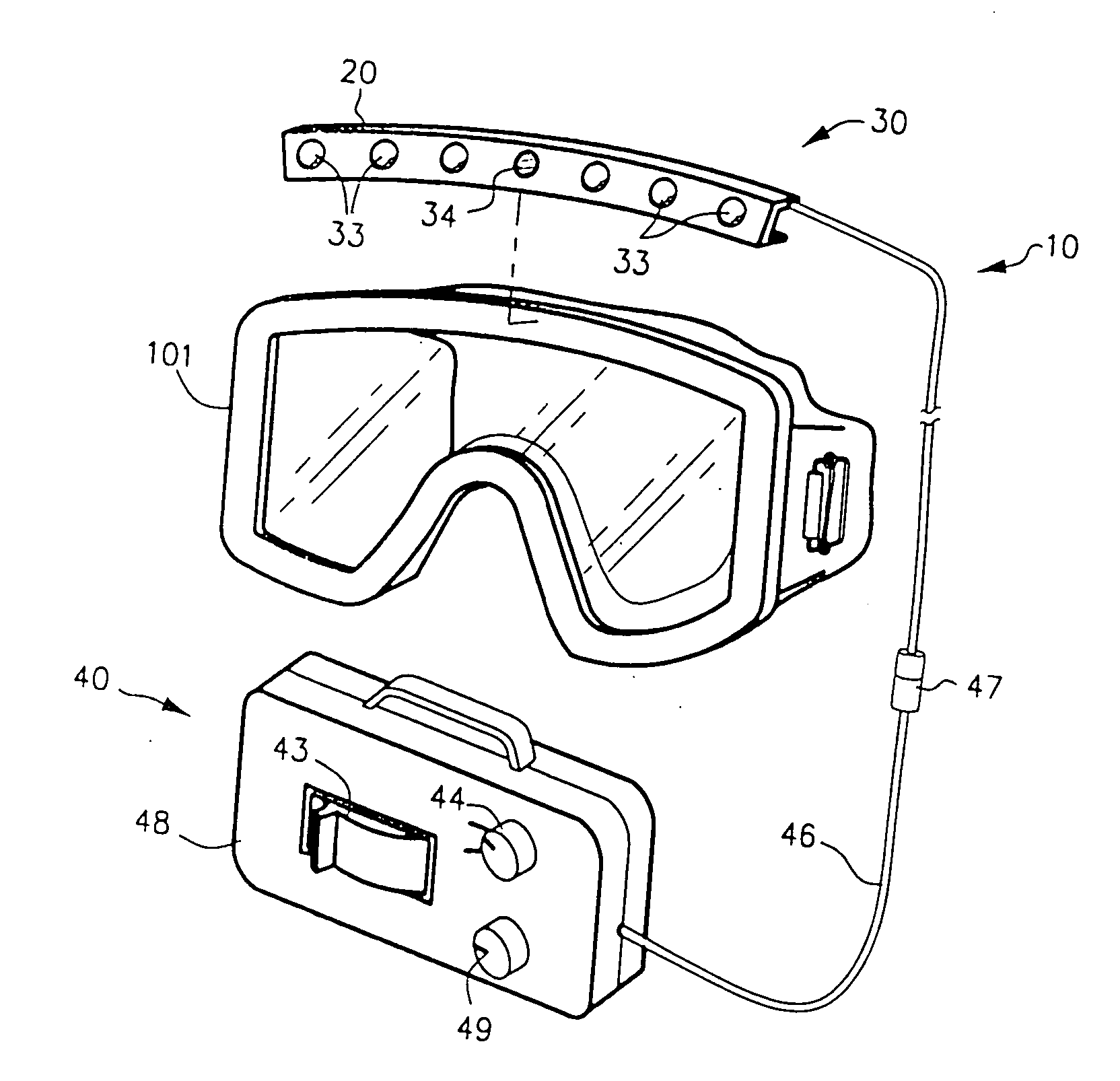
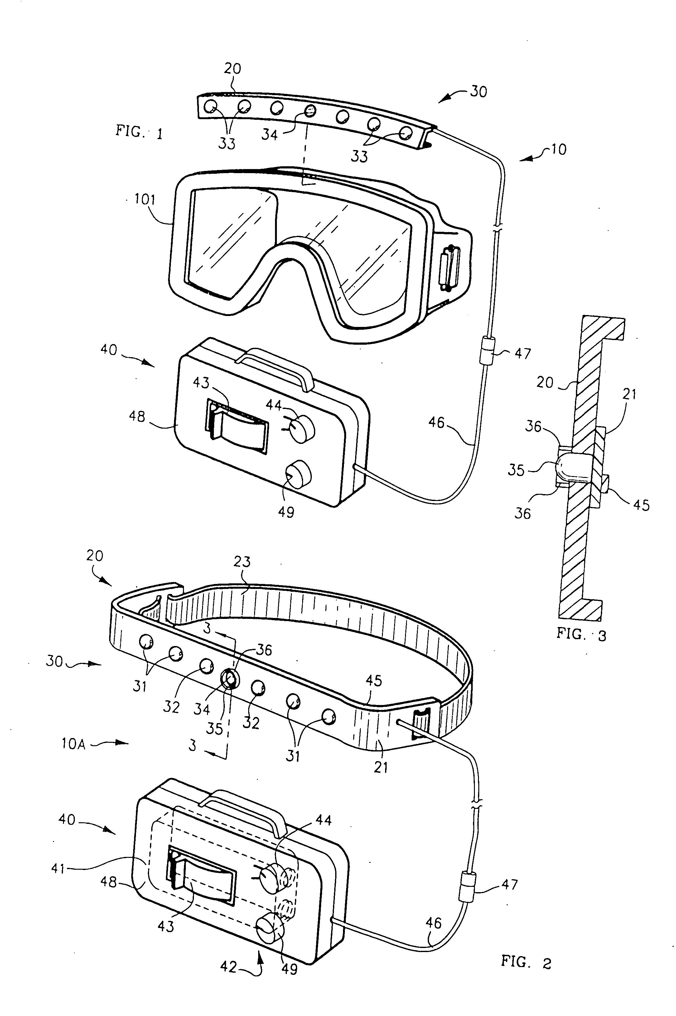
[0026]FIG. 1 is a view of the wearable light device 10 attached to goggles 101. FIG. 2 depicts an alternative preferred embodiment of wearable light device 10A adapted for wearing on the head. FIG. 3 is a sectional view of the light system 30 of FIG. 2, taken on line 3-3.

[0027] Device 10 includes a mount 20 for mounting upon an article of clothing, such as a garment such as a wetsuit, or such as an item of headwear such as goggles 101, or directly upon a body part such as an upper arm or forehead. Optionally, mount 20 can be molded separately, and be worn on the forehead, attached to elastic strap 23, as shown in FIG. 2, allowing light system 30 to remain a separately removable item.

[0028] Circuit Board 21 is attached to mount 20 and is for supporting light system 30. Light system 30 typically includes a plurality of light sources, such as light-emitting diodes (LEDs) 33 and at least one photo sensor 34, such as a photodiode 35, photocell, or similar device. In a preferred embodim...


PUM


Abstract

Wearable light device for providing additional light for activities in low light includes a wearable mount (20) including a light system (30) and power source (40). Light system (30) includes one or more arrays of light sources such as light-emitting diodes (33). Photo sensor (34) detects ambient light or emitted light returned from a reflective surface and causes control circuit (45) to dim light emission.

Description

CROSS-REFERENCE TO RELATED APPLICATIONS [0001] This application is a continuation-in-part of co-pending application Ser. No. 10 / 703,312, filed Nov. 7, 2003.FIELD OF THE INVENTION [0002] This invention relates in general to portable light devices and more specifically to a wearable light device to enhance vision while participating in activities under low light conditions. BACKGROUND OF THE INVENTION [0003] It is well known that wearable light devices have advantages over handheld flashlights for night-time activities. A wearable light device leaves both hands free for carrying articles or doing other work, or for simply swinging naturally while running or walking. A light worn on the forehead has the further advantage of illuminating the center of the wearer's field of vision. [0004] A familiar disadvantage of forehead-worn light devices is that, because the main light beam is emitted largely parallel to the direction of gaze, looking toward a reflective surface causes the beam to b...

Claims


Application Information

Patent Timeline
IPC IPC(8): F21L14/00F21V21/08F21V21/084F21V23/04G02C11/04G09G5/00
CPCF21L14/00G02C11/04F21Y2101/02F21V23/0442F21V23/0464F21Y2115/10A42B3/044
Inventor CUGINI, MARIOGIUSTI, RALPHTRACY, REXSERAFIN, CLEMENT
Owner FOXFURY
Why Eureka
Try Eureka