Spade drill insert having curved cutting edges

a cutting edge and drill bit technology, applied in the field of drill bit inserts, can solve the problems of less efficient cutting at the outside diameter of the spade drill bit, and the geometry of the straight cutting edge of prior art spade bit holes is apt to be susceptible to chatter, so as to improve the formation of chips

Active Publication Date: 2005-05-12
ALLIED MASCH & ENG CORP
View PDF19 Cites 12 Cited by
  • Summary
  • Abstract
  • Description
  • Claims
  • Application Information

AI Technical Summary

Benefits of technology

[0005] The spade drill of the present invention provides improved chip formation. This and other advantages over the prior art are provided by a drill insert comprising a drill insert body having a first end opposite a second end, a first face side opposite and parallel to a second face side, and a first land side opposite a second land side, the first and second land sides formed between the ends and the face sides; wherein the second end comprises at least two cutting edges formed transverse to each other, wherein each cutting edge is curved; and a groove formed in each cutting face adjacent the cutting edge, the groove having a trough substantially parallel to a plane formed through the abutting edges.

Problems solved by technology

One problem with prior art spade drill inserts is that the straight cutting edges do not efficiently form and / or transport chips during drilling operations.
Another problem with prior art inserts utilizing a corner clip clearance, the furthermost outside cutting edge is closer to the centerline of the lip thus being closer to a neutral or less positive rake geometry, especially when an oversized corner clip is utilized.
This results in less efficient cutting at the outside diameter of the spade drill insert.
A further problem with the prior art inserts is that the straight cutting edge chip formation is not tight which requires that the operational ranges of the tool to be narrowly defined for proper tool operation.
In addition, the geometry of the straight cutting edges of prior art spade drills are apt to be susceptible to chatter primarily due to the chip formation energy along rotating symmetrical planes at a constant speed developing harmonics at various operating speeds depending on the material being cut and the natural frequency of the tool and system.
This may result in the operator having to change the operating conditions of the drilling procedure to less than optimal ranges.

Method used


Image

  • Spade drill insert having curved cutting edges
  • Spade drill insert having curved cutting edges
  • Spade drill insert having curved cutting edges

Examples


first embodiment

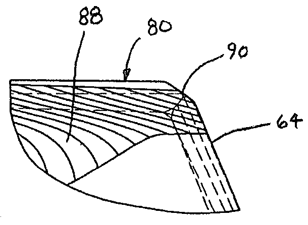
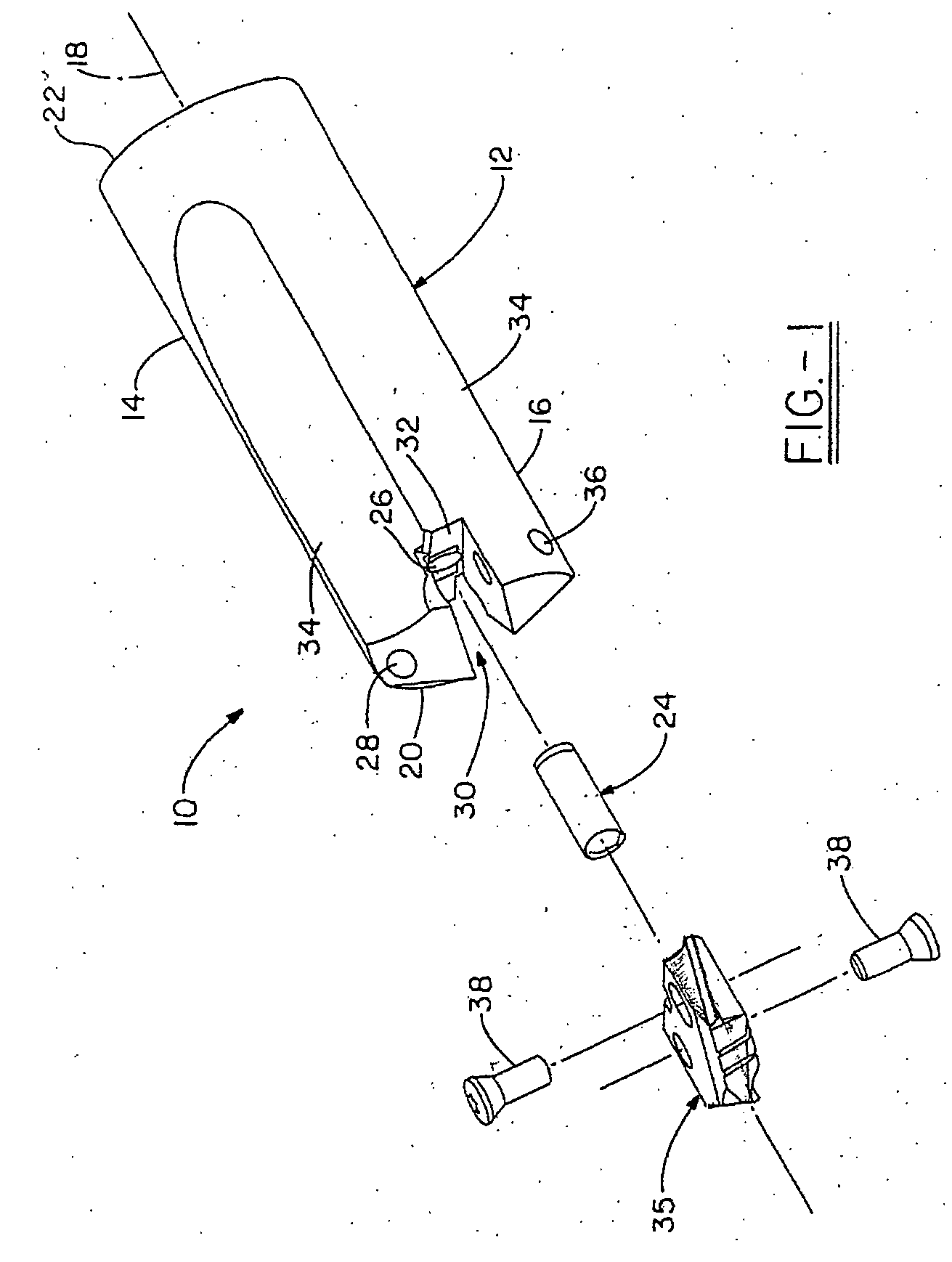
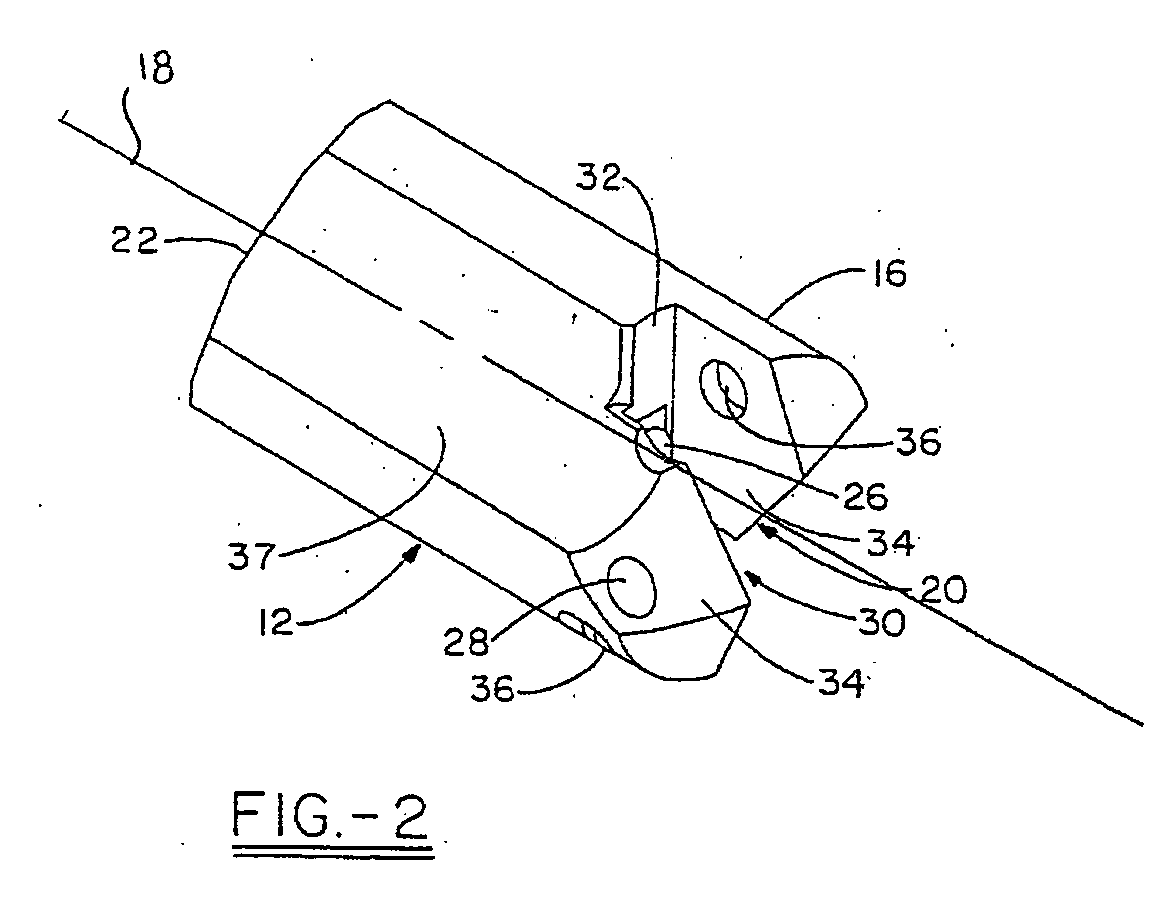
[0018] Turning to FIGS. 3A-3G, the spade drill insert 35 is shown. The drill insert 35 comprises cutting edges 64 on its upper surface generally in the form of an obtuse V-shape, with a cutting edge 64 on each either side of the chisel 62 and radially outward from a web thin 63. Each cutting edge 64 is curved and formed in a cutting edge plane such that the planes formed through the cutting edges 64 are transverse to each other and form the included angle. The cutting edges 64 are curved in the direction of rotation.

[0019] The curved cutting edges 64 may include a plurality of cutting components such as chip breakers 66, which cooperate together to provide the desired cutting surface for the material and / or drilling application. The insert 35 further comprises a pair of connection surfaces 68, or faces, on opposite sides of the insert 35 that are parallel to each other and provide a register surface for the clamping arms 34 of the holder 12. A groove 65, also referred to as the lip,...

second embodiment

[0025] Referring now to FIGS. 4A-4E, the spade drill insert 35′ is shown having curved cutting edges 64′ with an increased radial rake angle. The increased curvature allows for more variation in rake angle for different geometries.

[0026] In the previous embodiment, the curved cutting edge 64′ did not extend beyond an extended plane of the connection surface 68 of the insert 35. As best shown in FIGS. 5A-5C, the increased radial rake curved cutting edge 64′ of the insert 35′ extends well beyond the extended plane of the connection surface 68 of the insert 35′. This feature allows a longer cutting edge for the same diameter hole which helps increase cutting efficiency and prolongs the life of the cutting edge by spreading out the work along a longer cutting edge. The extended curved cutting edge also helps further reduce chatter by canceling out more harmonics associated with the drilling operation. Another benefit of the feature is that the parallel helical margin 82′ is adjacent the...


PUM

PropertyMeasurementUnit
radial rake angleaaaaaaaaaa
axial rake angleaaaaaaaaaa
widthaaaaaaaaaa

Abstract

A spade drill insert and drilling tool assembly is provided wherein the spade drill insert body comprises curved cutting edges and a lip groove having a trough substantially parallel to a plane formed through each adjacent curved cutting edge, which provides a significant improvement in chip formation during cutting operations.

Description

TECHNICAL FIELD [0001] This application claims the benefit of U.S. provisional patent application Ser. No. 60 / 518,556, filed Nov. 7, 2003, and is hereby incorporated by reference. The invention relates generally to a spade drill insert to be placed into a tool holder for boring holes into metals. More specifically, the invention relates to a spade drill insert having curved cutting edges which provide a significant improvement in chip formation over existing prior art spade drill inserts. BACKGROUND OF THE INVENTION [0002] Drilling systems are frequently used to provide cylindrical holes in metallic workpieces. The cutting or boring action of the drill system may be carried out by an elongated, substantially cylindrical drilling tool, such as a combination of a tool holder and a spade drill insert, which is selectively attached thereto. Such an arrangement may then be used in an application wherein one end of the tool holder is securely mounted in a driving apparatus, which rotates ...

Claims


Application Information

Patent Timeline
Patent Type & Authority Applications(United States)
IPC IPC(8): B23BB23B51/00
CPCB23B2251/02Y10T408/909B23B2251/082B23B2251/085B23B2251/14B23B2251/18B23B2251/48B23B2251/50B23B2260/072B23B2260/124B23B2270/08B23B51/0009Y10S408/713Y10T408/90993B23B2251/04B23B51/00035B23B51/00
Inventor MAST, WENDELL E.NUZZI, JOSEPH P.
Owner ALLIED MASCH & ENG CORP
Why Eureka
Try Eureka