Artificial facet joint and method

a technology of artificial facet joints and joints, applied in the field of artificial joints, can solve the problems that the artificial facet joints do not provide the rigidity that is necessary to support the spine, and achieve the effect of reducing friction coating and limiting joint movemen

Inactive Publication Date: 2005-05-12
SIMONSON PETER M
View PDF78 Cites 33 Cited by
  • Summary
  • Abstract
  • Description
  • Claims
  • Application Information

AI Technical Summary

Benefits of technology

[0006] An artificial facet joint includes a pair of connectors. Each connector comprises a first device connecting member having structure for sliding engagement of a rod and a second device connecting member having structure for sliding engagement of a screw. The first device connecting member and second device connecting member are rotatably engaged to one another. A spinal implant rod and a pair of spinal implant screws are provided. The first device connecting member of each of the connectors is slidably engaged to the rod. The second device connecting member of each of the connectors is slidably engaged to a respective one of the pair of spinal implant screws. The screws can be engaged to the pedicles on one lateral side of adjacent vertebra and the rods and connectors will limit movement of the joint. Structure for securing the spinal implant rod against axial movement relative to the spine can be provided. The structure for sliding engagement of the rod can be an aperture and the structure for sliding engagement of a screw can be an aperture. The apertures of the first device connecting member and the second device connecting member can comprise a reduced friction coating.

Problems solved by technology

Known artificial facet joints fail to provide the rigidity that is necessary to support the spine while permitting the flexibility to reassemble the facet joint.

Method used


Image

  • Artificial facet joint and method
  • Artificial facet joint and method
  • Artificial facet joint and method

Examples


Embodiment Construction

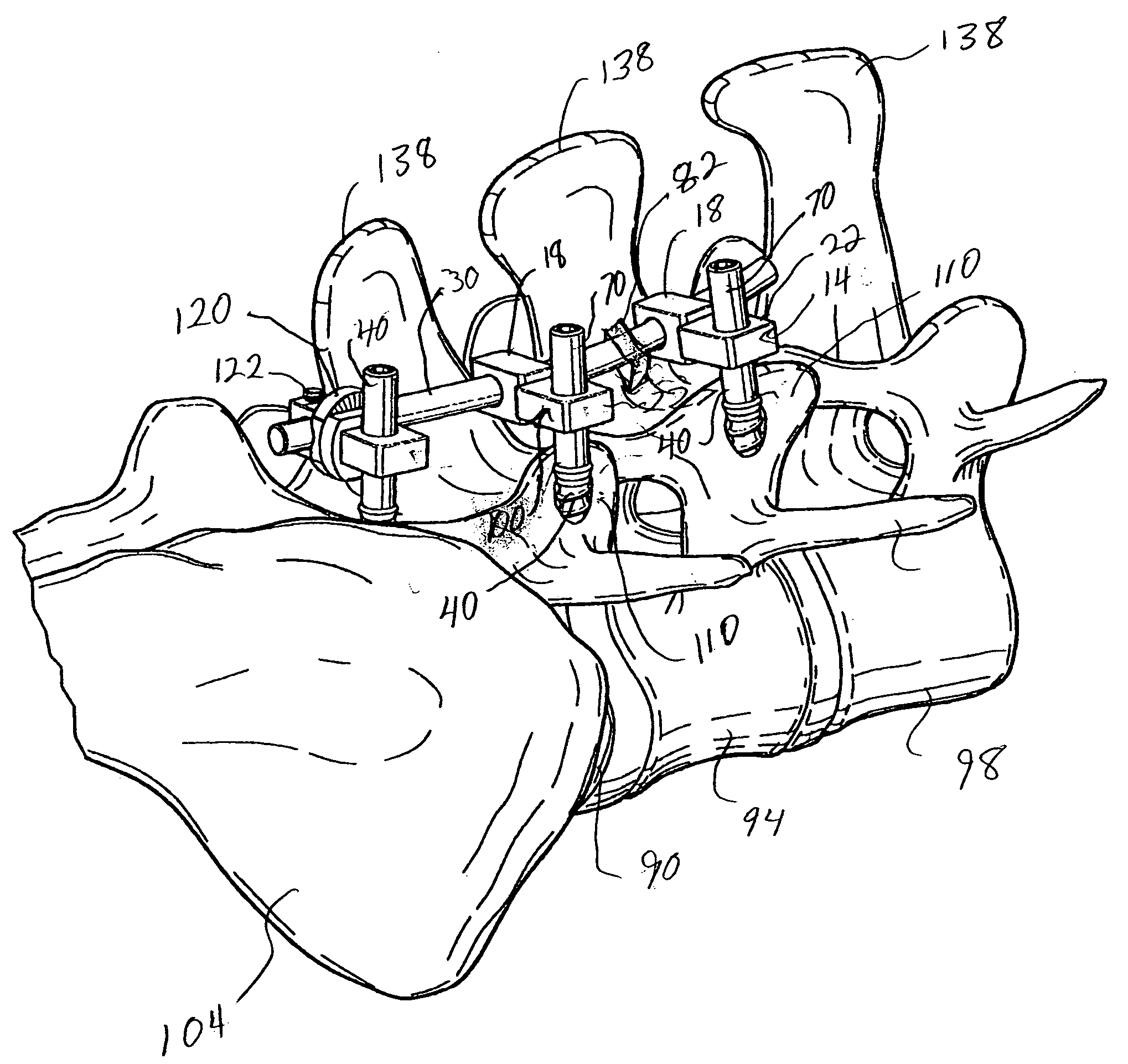
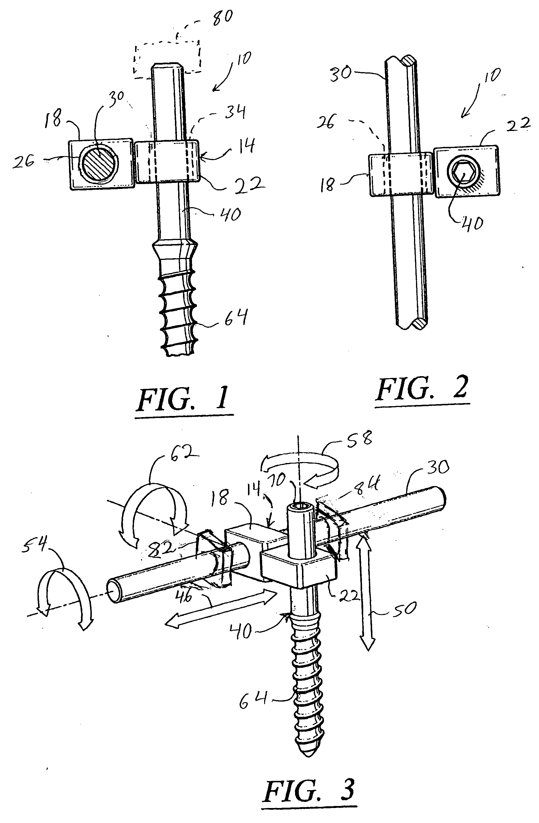
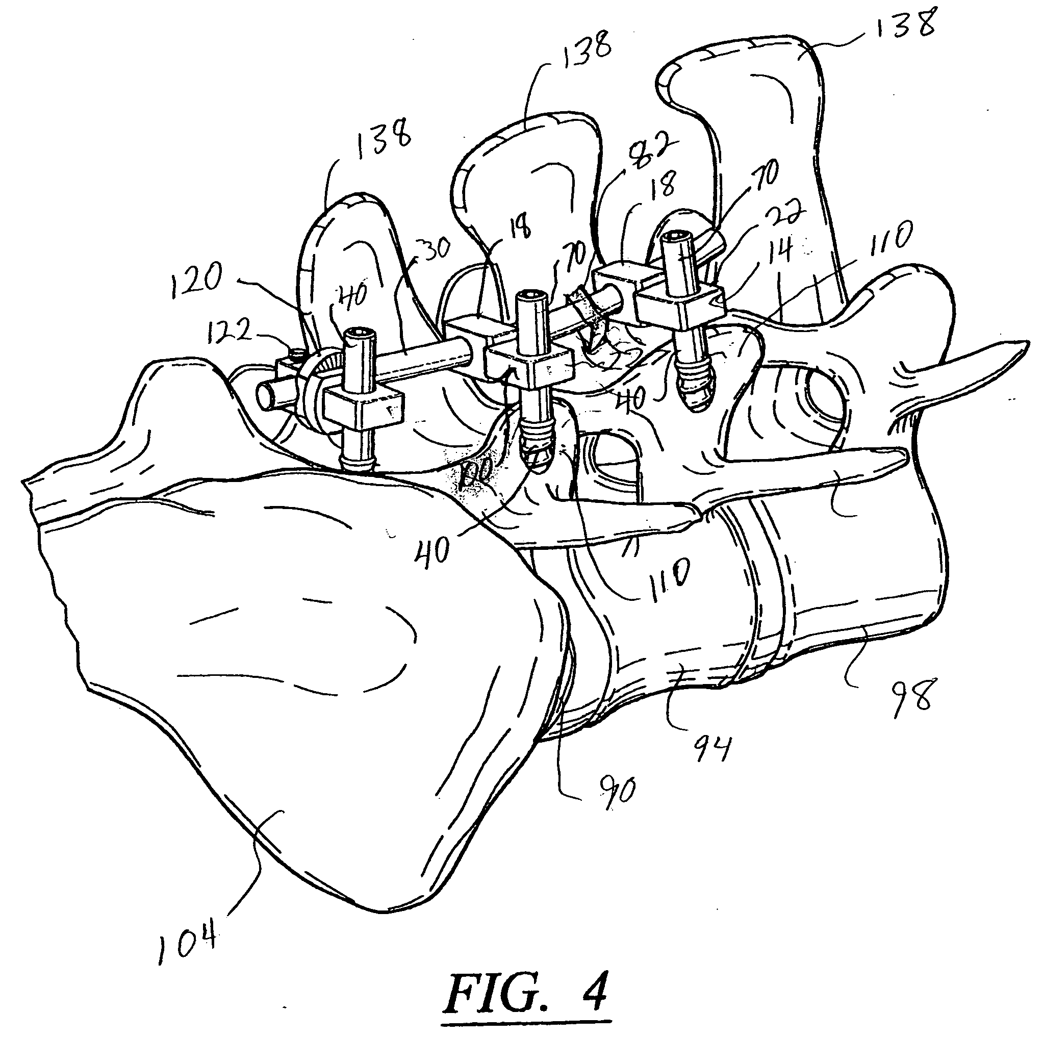
[0024] There is shown in FIGS. 1-3 a connector assembly for an artificial facet joint according to the invention. The connector assembly 10 includes a connector 14 having a first device connecting member 18 and a second device connecting member 22. The first device connecting member 18 has structure for sliding engagement of a spinal implant rod 30. The second device connecting member 22 has structure for sliding engagement of a spinal implant screw 40. The structure for slidably engaging the spinal implant rod 30 can be an aperture 26 for receiving the rod 30. The structure for slidably engaging the spinal implant screw 40 can be an aperture 34 for receiving the screw 40. Other structure is possible. The apertures 26 and 34 can be larger in diameter than the cross-sectional diameter of the rod 38 and screw 40, if desired, to permit movement of the first device connecting member 18 relative to the rod 30 as shown by arrow 46 in FIG. 3, as well as transverse movement to the extent of...


PUM


Abstract

An artificial facet joint includes a pair of connectors, each having a first device connecting member having structure for slidably engaging a rod, and a second device connecting member having an aperture for slidably engaging a screw. The first and second device connecting members are rotatably engaged to one another. A spinal implant and spinal implant screws are also provided. The first device connecting member of each connector is slidably engaged to the rod and the second device connecting member of each connector is slidably engaged to a respective one of the pair of spinal implant screws, whereby the screws can be engaged to the pedicles on one lateral side of adjacent vertebrae and the rod and connectors will limit movement of the joint. Another artificial facet joint can be provided on another lateral side of the adjacent vertebrae. A transverse member can be connected between the rods on each lateral side of the vertebrae.

Description

CROSS-REFERENCE TO RELATED APPLICATIONS [0001] Not applicable. STATEMENT REGARDING FEDERALLY SPONSORED RESEARCH OR DEVELOPMENT [0002] Not applicable. FIELD OF THE INVENTION [0003] This invention relates generally to the field of artificial joints and more particularly to artificial joints and ligaments. BACKGROUND OF THE INVENTION [0004] Each vertebra in the human spine has two sets of joints which interact with adjacent upper and lower joints. These joints are known as the facet joints, and are otherwise known as the zygapophyseal or apophyseal joints. Two joints are formed on each lateral side of the vertebra. The superior articular facet faces upward and the inferior articular facet faces downward, such that the superior articular facet of a lower vertebrae abuts the inferior articular facet of an adjacent upper vertebrae. The facet joints are located on the posterior of the spine adjacent the pedicle, lamina, and transverse process. The facet joints generally are hinge-like and ...

Claims


Application Information

Patent Timeline
Patent Type & Authority Applications(United States)
IPC IPC(8): A61B17/56A61B17/58A61B17/70A61F2/30
CPCA61B17/7041A61B17/7055A61B17/7049
Inventor SIMONSON, PETER M.
Owner SIMONSON PETER M
Why Eureka
Try Eureka