
Joint brace adjustable device

a joint brace and adjustable technology, applied in the direction of screws, nuts, bolts, etc., can solve the problems of too complicated operation process, increased burden on increased risk of injury to knee joints and elbow joints, so as to increase the adaptability of the joint brace fixer

Inactive Publication Date: 2010-05-27
HUNTEX
View PDF1 Cites 11 Cited by
  • Summary
  • Abstract
  • Description
  • Claims
  • Application Information

AI Technical Summary

Benefits of technology

[0004]One objective of the present invention is to provide a joint brace adjustable device, which adopts a distinct structure to replace the conventional complicated structure, and which is applied to fixing the joint angle and limiting the joint movement, and which can increase the adaptability of the joint brace fixer.
[0006]Via the abovementioned structure, the present invention has the following advantages over the conventional technology:
[0007]1. Greatly simplifying the structure, effectively reduce the cost, and favoring mass-production;

Problems solved by technology

Among them, the knee joints and the elbow joints are more heavily burdened and more likely to be hurt.
However, the structure is too complicated, and the operation process thereof is too troublesome.
The application thereof is only using the engaging element to fix the position of the second plate, but the cost thereof increases because the structure becomes further complicated.

Method used


Image

  • Joint brace adjustable device
  • Joint brace adjustable device
  • Joint brace adjustable device

Examples


Embodiment Construction

[0017]Below are described in detail the technical contents of the present invention.

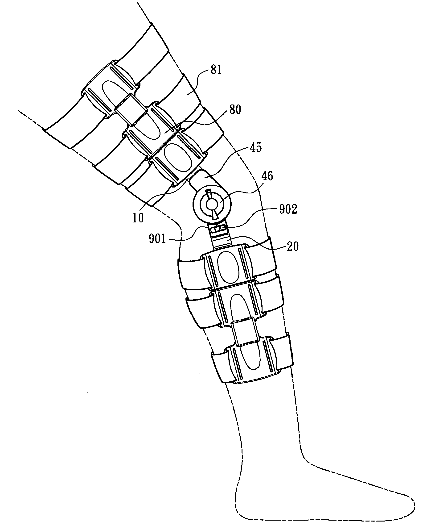
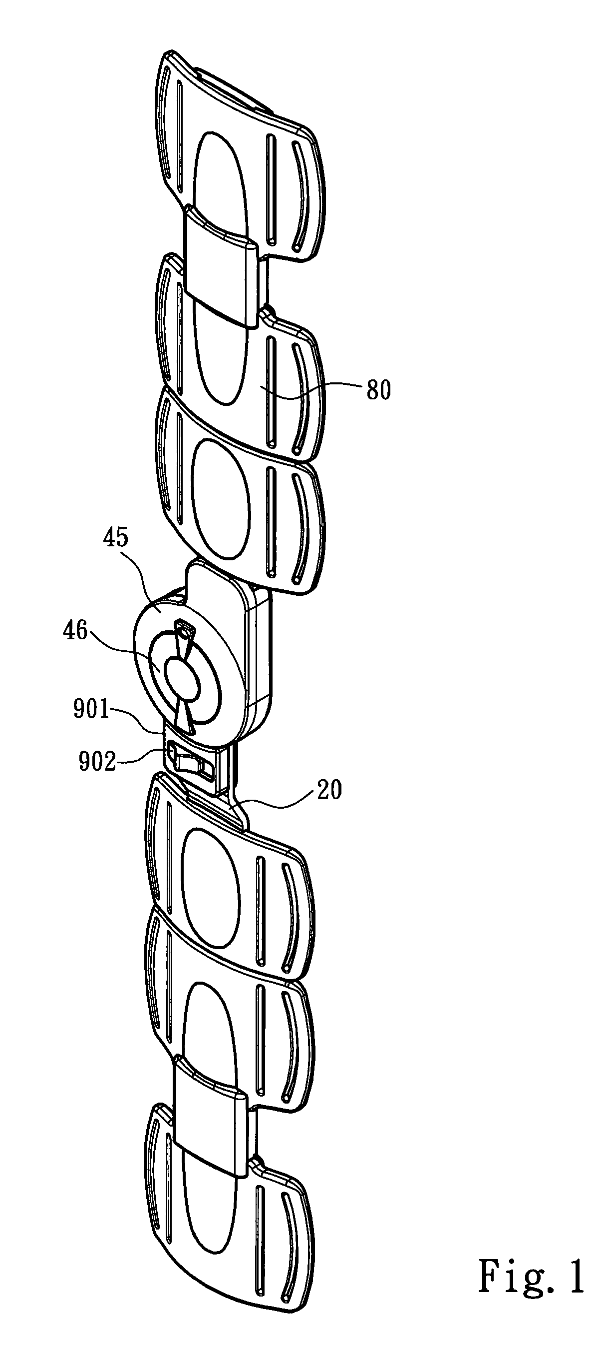
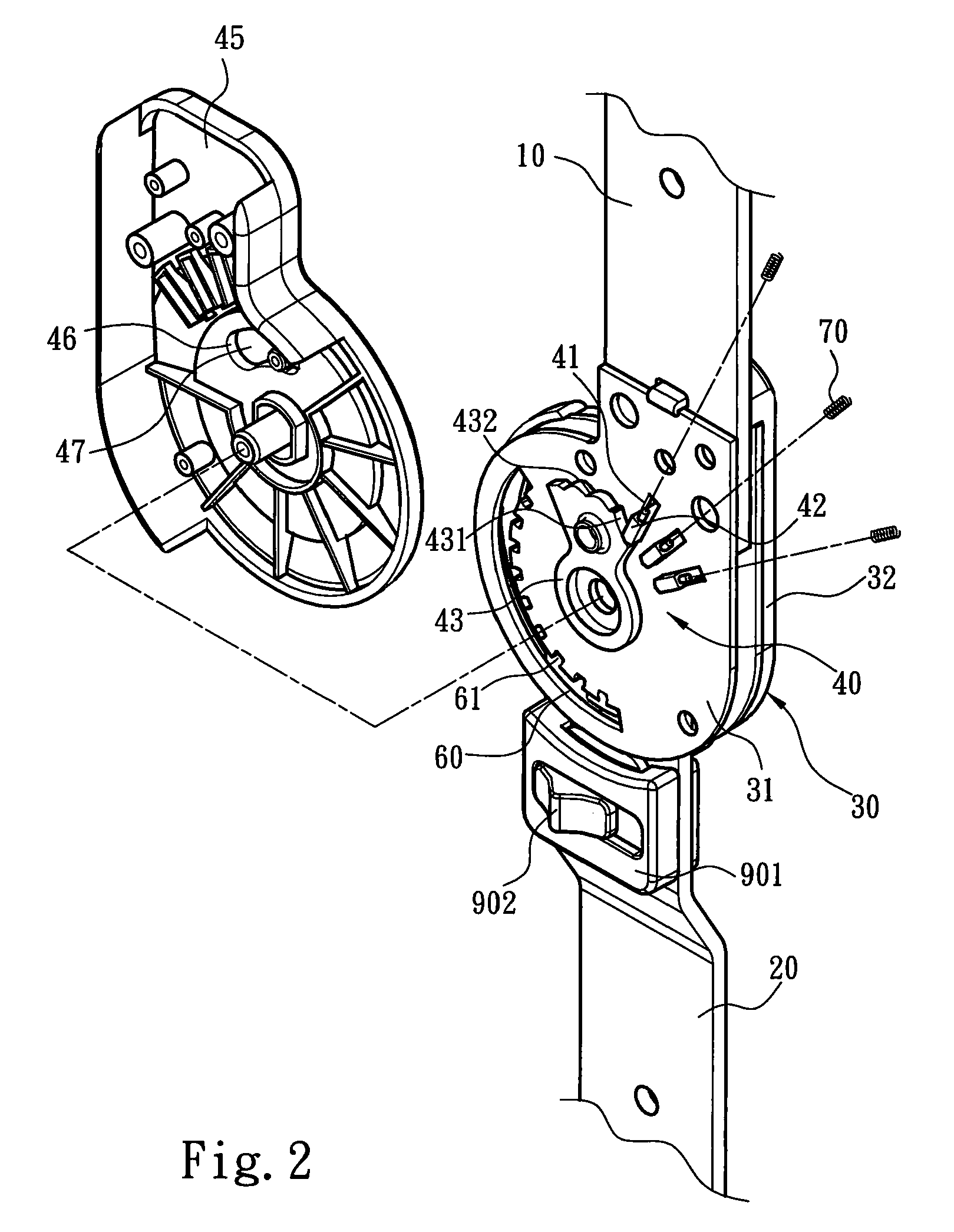
[0018]Firstly is described the relationship of the primary components. Refer to FIGS. 1-4. The joint brace adjustable device of the present invention comprises a first brace 10, a second brace 20, and a pivotal disc 30 connected with one end of the first brace 10 and pivotally coupled to one end of the second brace 20. The pivotal disc 30 has a motion-limit member 40 limiting the angle by which the second brace 20 rotates with respect to the first brace 10 with the pivotal disc 30 being the axis. The pivotal disc 30 has a positioning slot 60, and the positioning slot 60 has a plurality of positioning notches 61. The positioning notch 61 cooperates with a positioning member 51 to fix the second brace 20, and thus the first brace 10 and the second brace 20 contains a specified angle. The present invention is characterized in that the motion-limit member 40 has a plurality of position-fix slots 41 forme...


PUM


Abstract

The present invention discloses a pivotal disc is pivotally coupled to a first brace and a second brace. The pivotal disc has a motion-limit member and a positioning member limiting the angle by which the second brace rotates with respect to the first brace with the pivotal disc being the axis and fixing the angle between the first and second braces. The present invention is characterized in that the motion-limit member uses a range-adjust member to push a slide block and determine the range that a block portion of the second brace is blocked by the slide block, and that the positioning member uses a switch knob actuates on end of a positioning rod to engage with or depart from a positioning notch on the pivotal disc, and that the pivotal disc has two limit elements to define the maximum movement range of the first brace and the second brace.

Description

FIELD OF THE INVENTION[0001]The present invention relates to a joint brace adjustable device, particularly to a device to fix the angle of a joint or limit the movement of a joint.BACKGROUND OF THE INVENTION[0002]Joints are the pivots of our bodies, whereby we can perform various movements. Among them, the knee joints and the elbow joints are more heavily burdened and more likely to be hurt.[0003]Thus, there are various joint braces invented. The joint braces may be categorized into the prophylactic braces preventing from joint hurts, the functional braces limiting joint movements after surgery, and the rehabilitative braces fixing the angle of a joint during rehabilitation. The abovementioned joint braces respectively have different structures to implement different functions. There are also multi-functional joint braces. For example, a Taiwan patent No. M311408 disclosed an “Adjusting Device for Knee Joint Fixer (1)”, wherein the slide way thereof has insert slots, and two positio...

Claims


Application Information

Patent Timeline
IPC IPC(8): A61F5/00
CPCA61F5/0125A61F2005/0158A61F2005/0167Y10T24/44744Y10T24/44573Y10T24/4634Y10T403/32327
Inventor CHAO, CHIA-CHANG
Owner HUNTEX
Learn More