Method of producing fuses

a technology of fuses and fuses, applied in the field of fuses production, can solve the problems of increasing the number of defective fuses, reducing productivity, and becoming difficult and troublesome to produce fuses, so as to prevent flexural deformation of lead wires and minimize the generation of bad quality fuses

Inactive Publication Date: 2005-05-19
PI
View PDF2 Cites 8 Cited by
  • Summary
  • Abstract
  • Description
  • Claims
  • Application Information

AI Technical Summary

Benefits of technology

[0011] Therefore, the present invention has been made in view of the problems inherent in the prior art method, and it is an object of the present invention to provide a method for producing quality fuses in a large quantity and in a highly automated fashion.
[0012] It is another object of the present invention to provide a method for producing fuses which is capable of preventing a flexural deformation of lead wires during the production of the fuses, thus minimizing generation of bad quality fuses.

Problems solved by technology

As well known to those skilled in the art, a fuse has a fusible metal connector, which is melted by an excessive electric current, and thus is broken.
However, the aforesaid conventional method for producing fuses has problems in that a great deal of manual work is required during production of the fuses, thus resulting in a reduced productivity and an increased number of defective fuses.
Consequently, it becomes difficult and troublesome to produce the fuses.
Furthermore, it takes a lot of time to produce the fuses, which leads to decreased productivity.
Besides, the lead wire tends to be easily bent when it is forcibly inserted into the through-hole of the insulator base, and there is a tendency that the lead wire may be unwantedly separated from the through-hole while the fuse is produced or used.
However, the aforesaid conventional method for producing fuses also has problems in that a great deal of manual work is required in the course of unwinding a rolled lead wire having a circular section, cutting the unwound lead wire to a prescribed length, arranging the cut lead wires in an injection mold, and injecting a resin into the injection mold.
Furthermore, the fuse has to be produced one at a time, which leads to a prolonged production time and a decreased productivity.
This makes it dificult to affix the lead wire at the desired position.
Especially, the lead wire has a tendency to return to its original rolled form even after it is fixed to the insulator base, which may result in production of defective fuses.

Method used


Image

  • Method of producing fuses
  • Method of producing fuses
  • Method of producing fuses

Examples


Embodiment Construction

[0023] A preferred method for producing fuses according to the present invention will now be described with reference to the accompanying drawings. In the present specification, the term “blank” denotes a half-finished product obtained by pressing a metal sheet into a plurality of pairs of lead conductors.

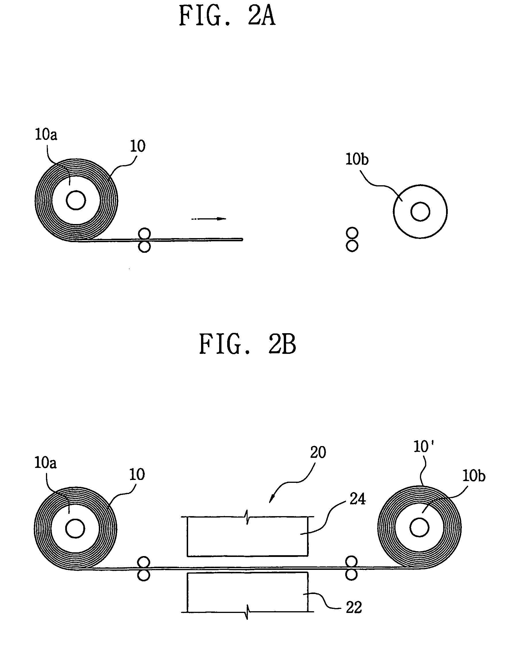
[0024]FIGS. 2A to 2H show a series of steps employed in the method for producing fuses according to a preferred embodiment of the present invention, and FIGS. 3A to 3E show configuration of metal sheets formed at the respective step of the inventive method.

[0025] The fuse production method according to the present invention makes use of a metal sheet 10, which may be a rolled continuous strip as shown in FIG. 2A. The metal sheet 10 is intermittently unwound from a supply reel 10a and transferred to a take-up reel 10b. One example of the metal sheet 10 may be a copper sheet. The width and length of the metal sheet 10 are appropriately determined depending upon the size of a fuse t...


PUM

PropertyMeasurementUnit
lengthaaaaaaaaaa
electric currentaaaaaaaaaa
structuresaaaaaaaaaa

Abstract

A method is provided for producing fuses with an increased yield rate and in a highly automated fashion. The method comprises the steps of processing a metal sheet into a blank having a plurality of continuously distributed pairs of lead conductors, molding an insulator base integrally with each pair of the lead conductors, electrically interconnecting the lead conductors of the respective conductor pair with a fusible connector, and severing the lead conductors from the blank. Additionally, a protection cap is coupled to the insulator base in such a manner that the cap can enclose the fusible connector in its entirety.

Description

TECHNICAL FIELD [0001] The present invention relates to a method for producing fuses, and more particularly to a method for producing quality fuses with an increased yield and in a highly automated fashion. BACKGROUND ART [0002] As well known to those skilled in the art, a fuse has a fusible metal connector, which is melted by an excessive electric current, and thus is broken. When electric current having more than a prescribed value flows, the fusible metal connector is broken to automatically shut off the electric current so that electronic parts and electric circuits are protected. Such a fuse has been developed in various structures and forms. Recently, a micro fuse applicable to a small-sized electronic product has been developed. [0003] A conventional micro fuse (hereinafter, referred simply to as “fuse”) is shown, in cross section, in FIG. 1. As shown in FIG. 1, the fuse 1 includes an insulator base 3. The insulator base 3 is made up of a disc-shaped member with a prescribed ...

Claims


Application Information

Patent Timeline
Patent Type & Authority Applications(United States)
IPC IPC(8): H01H11/00H01H69/02H01H85/041H01H85/04
CPCH01H11/0056H01H69/02H01H85/0417Y10T29/49204Y10T29/49107Y10T29/49121Y10T29/49158H01H85/04
Inventor KIM, CHANG-IL
Owner PI
Why Eureka
Try Eureka