

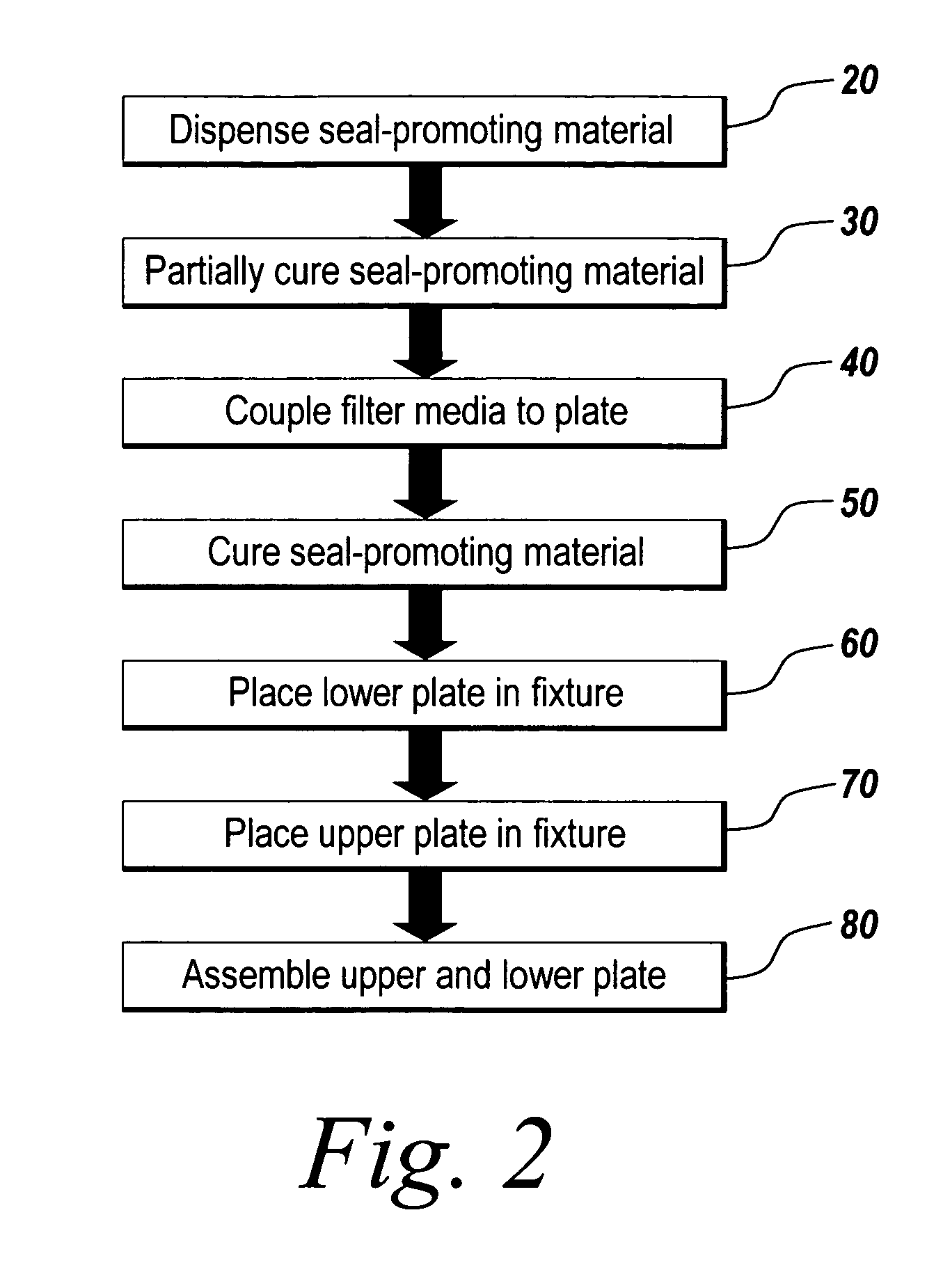
Method of assembling a filtration plate
a filtration test and plate assembly technology, applied in the field of single or multiwell filtration test plates, can solve the problems of separating the filter media from the plate, leakage of liquid being filtered from the well, and tearing of the filter media, so as to achieve enhanced sealing between the upper and lower plates of the filtration pla
- Summary
- Abstract
- Description
- Claims
- Application Information
AI Technical Summary
Benefits of technology
Problems solved by technology
Method used
Image

Examples
Embodiment Construction
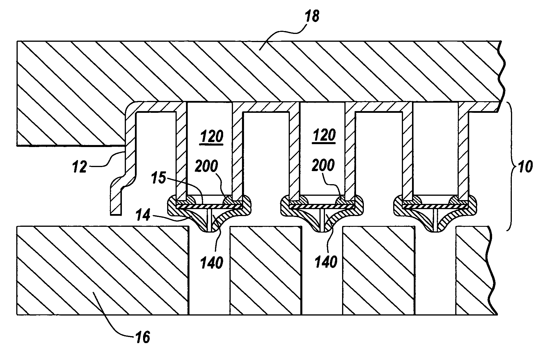
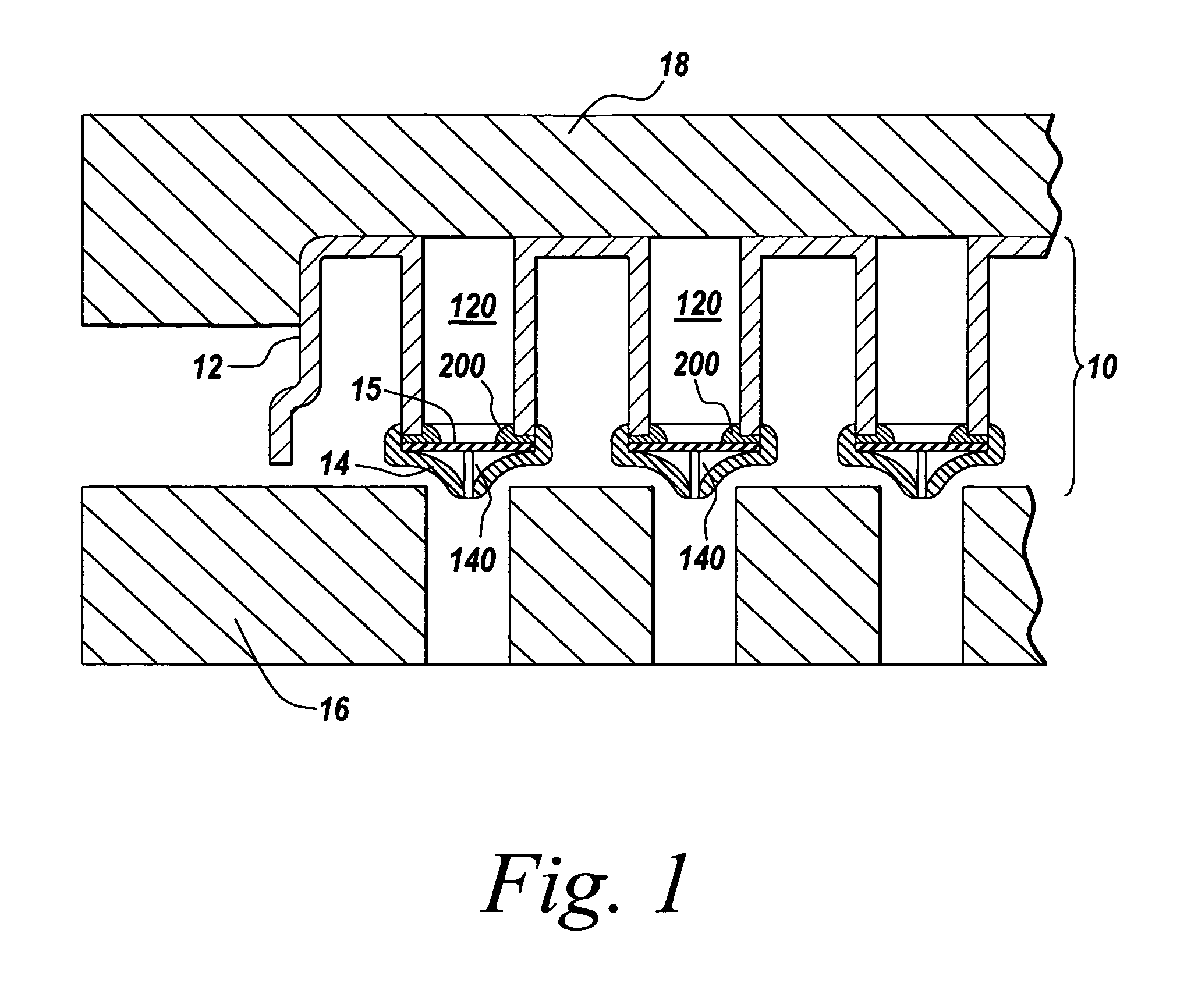
[0021] In an illustrative embodiment, an improved filtration plate and method of assembling the filtration plate are provided. The filtration plate and method of assembling the filtration plate integrate a seal at an interface between an upper plate and filter media and / or a lower plate and a filter media using a seal-promoting material, which may form an O-ring upon curing of the seal-promoting material. The seal-promoting material also effectively secures the filter media to the upper and / or lower plate. The present invention will be described below relative to an illustrative embodiment. Those skilled in the art will appreciate that the present invention may be implemented in a number of different applications and embodiments and is not specifically limited in its application to the particular embodiments depicted herein.
[0022]FIG. 1 illustrates a multi-well filtration plate 10 suitable for implementing an illustrative embodiment of the invention, though one skilled in the art w...
PUM
| Property | Measurement | Unit |
|---|---|---|
| diameter | aaaaa | aaaaa |
| electromagnetic field | aaaaa | aaaaa |
| perimeter | aaaaa | aaaaa |
Abstract
Description
Claims
Application Information