Two-layer wide-band meander-line polarizer

Inactive Publication Date: 2005-05-19
COMSAT
View PDF9 Cites 11 Cited by
  • Summary
  • Abstract
  • Description
  • Claims
  • Application Information

AI Technical Summary

Benefits of technology

[0007] It is another object of the present invention to minimize a number of layers presen

Problems solved by technology

Such meander-line polarizers are expensive to manufacture and are undesirably thick.
However, the related art does not disclose or suggest use of a two-layer meander line polarizer, particularly one with low axial ratio over a wide bandwidth.
Thus, the aforementioned related art structure has at least the disad

Method used


Image

  • Two-layer wide-band meander-line polarizer
  • Two-layer wide-band meander-line polarizer
  • Two-layer wide-band meander-line polarizer

Examples


Example

[0016] Reference will now be made in detail to an illustrative, non-limiting embodiment of the present invention, examples of which are illustrated in the accompanying drawings. In the present invention, the terms are meant to have the definition provided in the specification, and are otherwise not limited by the specification.

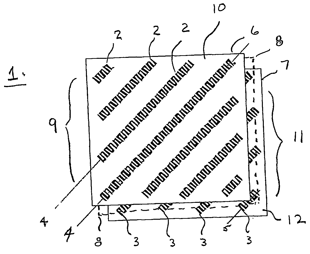
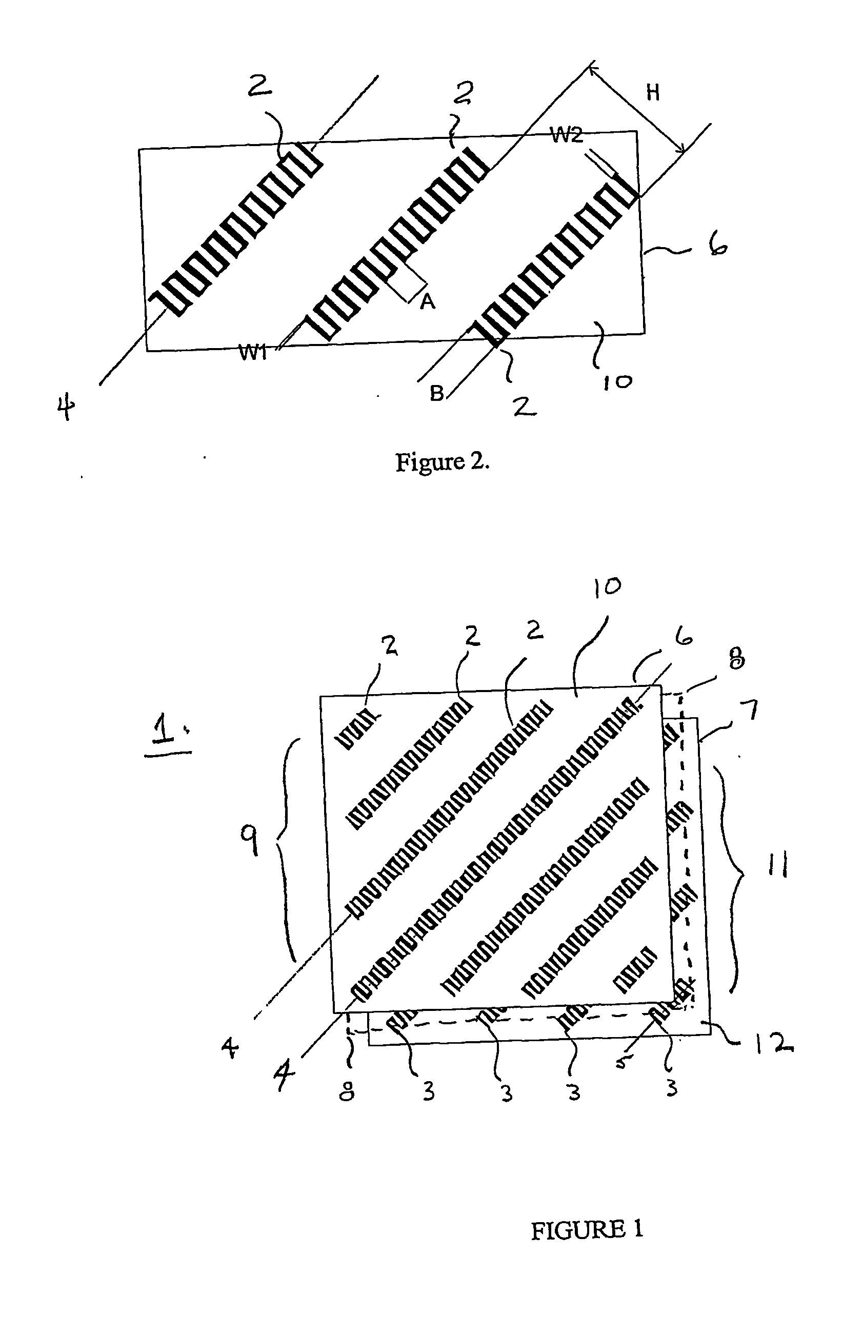
[0017] The present invention includes a first meander line polarization layer having a first conductive meander line array disposed on a major surface of a first substrate and a second meander line polarization layer having a second conductive meander line array disposed on a major surface of a second substrate. The two substrates are separated by a distance that is less than one quarter wavelength. In the illustrated example, the distance is 0.15 of a wavelength. The meander line polarizer layers introduce phase shifts and signal decomposition, which leads to decomposing the signals into two sets of orthogonal linear polarizations at phase quadratures to pro...


PUM


Abstract

A two-layer polarizer (6, 7) comprising a first substrate (10) having formed on a major surface thereof a first conductive meander line array (2) and a second substrate (12) having formed on a major surface thereof a second conductive meander line array (3). The first and second substrates are disposed as adjacent layers and are separated by a dielectric space (8). At least a portion of the first meander line array and a portion of said second meander line array are overlapping.

Description

[0001] This application claims the benefit of U.S. Provisional Application No. 60 / 283,917, filed Apr. 13, 2001, under 35 U.S.C. § 119(e).BACKGROUND OF THE INVENTION [0002] 1. Field of the Invention [0003] The present invention disclosure relates to a meander-line polarizer, particularly a polarizer having only two printed layers and operative to provide wide-band performance with a low axial ratio. The polarizer is especially useable in aperture-type antennas, particularly antennas operative to convert electromagnetic field polarization from linear to circular and from circular to linear. [0004] 2. Background of the Invention [0005] In the related art, two orthogonal senses of linear polarization in a multilayer printed circuit structure can be produced, as well as a single circular polarization using a multilayer printed circuit structure having a meander line conductor. Previous designs of meander line polarizers used 3 to 4 layers of printed circuits to achieve the required axial...

Claims


Application Information

Patent Timeline
IPC IPC(8): H01Q13/10H01Q15/14H01Q15/24
CPCH01Q13/10H01Q15/142H01Q15/244H01Q15/242H01Q15/24H01Q1/38
Inventor SUN, LIANG QZAGHOUL, AMIR I
Owner COMSAT
Why Eureka
Try Eureka